


STEERING VEHICLES with Six or Eight Wheels
Page 84
If you've noticed an error in this article please click here to report it so we can fix it.
A Resum4 of Recently Published Patent Specifications.
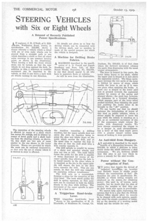
AN engineer, J. H. O'Neill, of 3, Hillside, Wellington Road, Jersey, in specification No. 318,686, shows a means whereby a vehicle which is fitted with six or even eight wheels can be steered from a straight path to one which describes a circle so that all wheel axles converge to one common turning point, as shown in the illustration. When leaving a kerb the front wheels alone can be turned, so that the rear wheels do not drag against the kerb. In addition to this, a sideways or crablike movement can be imparted to the vehicle, so that it can leave a kerb with all wheels turning in one direction.
The operation of the steering wheels is effected by means of a shaft which lies across the vehicle, and is rotated by means of bevel oafs and a shaft leading from the steering column, as shown. On this shaft are two sets of cams similar to the one shown in the lower diagram. Means are provided by which the cams can be rendered inoperative, so that only the set of wheels which it is desired to steer is effected. No details are given as to how the driving wheels can he connected with the driving shaft, and no mention is made of the special purpose for which the vehicle is designed.
A Machine for Drilling Brake Fabrics.
A. MACHINE described in the specification of A. D. Powell and Joseph Bradbury and Sons, Ltd., of New Street Works, Braintree, No. 318,779, is one that should appeal to all who have to maintain fleets of vehicles. As will be seen from the illustration,
the machine resembles a drilling machine, but the upper spindle cloth not carry the drill, its function being to press the shoe and fabric down on the guide which carries the drill, and at the saw; time to register the hole in the shoe so that the drill shall bore a hole exactly opposite it. The drill spindle is rotated by means of a chain and sprocket wheels, and does not rise or fall. The bush which forms the guide for the drill is capable of being depressed by means of the upper spindle, thus allowing the hole to be bored exactly in the place where it is required, as the pin in the upper spindle will ensure the hole in the shoe being opposite the drill. This pin can recede, so that the drill can complete its operation without interference.
The drill acts as a countersink, forming a place for the reception of the rivet head. The bush which guides the drill is spring operated, so that pressure can be exercised to hold the fabric closely to the shoe while drilling. The movement of the upper spindle is operated by a foot lever.
A Triggerless Hand-brake Lever.
THE triggerless hand-brake lever shown in the specification of H. 0. Hinchliffe, of Middleton St. George, Co.
Durham, No. 318,653, is of that class where the forward movement releases the pawl, thus dispensing with the usual trigger arrangement.•
The lever is formed in two parts the lower being keyed to its shaft, whilst the upper part is hinged to it just above the segmental ratchet. The hinge movement between the two parts of the lever is limited by means of stops, which enable the lever to act as if it were one piece when applying the brake. A pawl (A) is hinged to the lower part and is pressed towards the segmental ratchet by means of the spring and plunger shown ; the pawl has, however, an extension in a forward direction, which engages part of the lever when pushed forward, thus releasing the pawl and enabling the brake lever to be brought to the " off " position.
We can hardly say that we should welcome the introduction of levers of this kind on public vehicles, where a . driver might be required to leave his seat while the vehicle is standing on a hill, as an accidental movement of -one of the passengers might release the brake, with disastrous results. We have always considered the trigger to • be a danger in such circumstances. but a lever of this kind might prove even a greater danger unless some means of locking it were provided.
An Anti-skid from Hungary.
AN anti-skid is described in the speci ticatnin of a Hungarian inventor, No. 318,398, in which a skid-pan is introduced under the wheel whenever, a skid commences. We are, however, afraid that this planis not very likely to prove a remedy for the skid trouble.
Power without the Consumption of Fuel.
wE notice that despite the S'pread of technical knowftdge, an inventor (not British) hopes to obtain power without the consumption of fuel.He describes his plan in specification No. 318,089, in which falling weights are employed as the means for obtaining power ; this part is, of course, quite possible, but we doubt that his plan of raising the weights so that they can do their work over again is practicable.
We cannot help again expressing, the opinion that it is a pity that the British Patent Office should allow its records to be clogged with such patents, especially when the simple expedient of insisting on the showing of a working model would end the trouble for ever. .