


IS THE MECHANICAL GEA
Page 34
Page 35
Page 36
If you've noticed an error in this article please click here to report it so we can fix it.
a DOOMED?
SIGNS are not wanting that the mechanical system of transmission, as employed since the inception ot the motor vehicle, is being subjected to severe critical examination. Comparison is being made with the hydraulic system, which has given such a good account of itself in the operation of the auxiliaries in aircraft, and in the control of gun turrets. The advance in technique during the war period, when economics were not permitted to stand in the way of technical achievement, has been responsible for bringing such forms of transmission well within the economic sphere for application to road motor vehicles.
The table which follows is given to show the comparative requirements of the two systems, the hydraulic being of the hydrostatic type. Mechanical. Hydraulic.
Engine .. 1 1
Clutch .. .. I none Pump—hydraulic none 1 Gearbox—gears .. 8 none
Gearbox—reverse gears 1 none
Propeller shaft .. 1 none Conduit—hydraulic .. . none 1 Axle crown wheel and pinion.. 2 none
Differential gears .. .. 6 none Motor—forward, reverse and
brake .. none Totals .... 20 5 Characteristics of Two Types Hydraulic systems may be divided into two types— the hydrokinetic and the hydrostatic. The former functions as the result of the speed imparted to a fluid by an impeller, the fluid acting on a follower or turbine, which provides the necessary conversion to rotary mechanical motion In the second system, a fluid, usually oil, transmits pressure applied to it to mechanism which may have rotary or linear characteristics The hydrokinetic system has been applied to both stationary and transport machinery for a number of years. At the present time the hydrostatic system is not to be found in any type of road vehicle. Research was carried out a number of years ago, but the results obtained were not of sufficient significance to justify continuance of the work. Nevertheless, there is a
revival of interest in the system in America, with which the name of Ford is associated.
Of the two forms which the hydrokinetic type may take, the simplest is that which is introduced to take the place of the orthodox clutch. The origin of this type was the German Fottinger, which was used as a coupling between the prime mover and alternator in electric power generating plants, and for analogous purposes There were several other German makes, amongst which may be mentioned the Vulcan and the Voith.
The system was applied to road vehicles in this country by Sinclair. It has had such designations as the
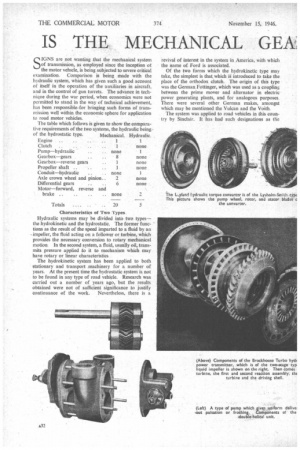
Fluid Flywheel, fluid drive, and hydraulic coupling. The characteristic of this system is the much-increased refinement of driving over the existing friction clutch system that it replaces. The acceleration characteristics are not so good as with the conventional clutch, and, further, it is never quite free, as there is always a tendency for the drag of the fluid to cause " creep." This latter point is emphasized in patent literature, and several patents have recently been taken out covering this specific feature.
The second type of hydrokinetic trans-mission is the torque converter, which not only takes the place of the clutch, but that of the gearbox too. It does not altogether succeed in this, as it cannot, in itself, provide a reverse gear, which must, therefore, be of the mechanical type. Further, it is admitted by the makers of the equipment that it is necessary to provide a, mechanical low-gear ratio for-vehicles which are called* upon to operate in particularly hilly districts.
The hydraulic difference between the Fluid Flywheel' and the torque converter is that, whilst the former comprises but two main elements—the impeller and turbine —the torque converter has a third—the reaction member.
In all hydrokinetic transmissions there is a speed loss of 3-5 per cent. In this connection, the Lysholm-Smith torque converter, as used by the Leyland concern, is provided with a conventional type of clutch which is hand operated to provide for top-gear engagement.
As applied by the Daimler concern, the system includes change-speed gears of the Wilson type, and in applications of the hydrokinetic torque converter in America, the conventional type of clutch was used to take care*of gear changing.
Recent developments of the hydrokinetic system are along the lines of a combination of the hydraulic torque converter and two epicyclic trains of gears, in conjunction with over-running clutches equivalent to free-wheel devices. The gripping of one or other of the planetary members provides for the different gear ratios in the manner customary with such gears, and in certain designs a reverse ratio is also arranged.
The addition of gears to the hydraulic system is an attempt to increase the efficiency of the whole by making the gears take over the duty at a point where the efficiency of the hydraulic system begins to fall off to an undesirable exen t.
Apart from types already mentioned, there are others, such as the Eaton, de Normanville and Vinter, to mention only a few in this country, and many others which emanate from America.
Speed-changing Systems
The tendency in the control of gear or speed changing is towards hydraulic means for operation, which is usually dependent upon some feature of vehicle operation, such as speed, engine torque, or manifold depression, the operating power being through the medium of an hydraulic pump. In most of the systems there is what is generally referred to as a " kick-down " change from top to the next lower speed. This is an over-riding manual control of the automatic operation by some function of running as previously referred to.
The general trend in design is towards a much speedier control of the change down from overdrive or top into a lower speed. It is generally considered that the conventional means for gear changing is rapidly falling behind the demands, not only of convenience, but in respect of road safety—at least, so far as America is concerned.
In some of the modern designs the vehicle is running with the equivalent of a free-wheel on top gear, but the tendency is to eliminate this feature, because it prevents the use of the engine as-a-brake: Changing ‘doiirn from top to the next speed automatically puts the transmission into "fixed" gear,"'ffiaking the engine' available for braking purposes: A recent patent taken out by Crossley Motors, Ltd.,; adds emphasis to this point. Another trend lies in the .endeavour. to ,eliminate the cessation' of torque' diiringl the ciperation of speed changing, the effect of which interruption has not been appreciated in the past. Sustained torque is a feature of a number of recent patents, that of the de Normanvie specification being one in particular.
A further modern development is the step following from the "overdrive" common on American vehicles. It is termed the " underdrive" and can be used only on machines having a power-weight ratio in advance of about 40 lb. per b.h.p. The difference between the two systems is that, with an overdrive, the rear-axle ratio remains unaltered, whereas, with the underdrive, the ratio is raised, so that the speed of the propeller shaft is reduced, with a consequent decrease in vibration.
It was as far back as 1912 that the hydrostatic system of transmission was tested in London. When the scheme—patented by Hugo Lentz, a German—was installed in a public-service vehicle (British patent No. 15,781) it was, at the time, found to be impracticable, on account of the impossibility of retaining the oil, and of preventing t h e entry of air into the circuit. Such defects, however, would not necessarily exist to-day.
In the Lentz construction there were two engine-driven, vane-type pumps, one being double the capacity of the other. On each of the rear-axle half shafts was a reverse pump which acted as a motor; these were fed by the enginedriven pumps. This arrangement eliminated the conventional crown wheel and pinion, and differential gears.
The smaller of the two main pumps supplying the axle motors provided first speed, and the larger pump second speed;. a third speed was derived from both pumps working in conjunction. The combined capacity of the rear-axle motors was three times that of the two main pumps, so that a rear-axle reduction of 3 to I was provided. There was a valve which controlled the supply of fluid to the motors, in both forward and reverse gears, and by virtue of its throttling capacity, a powerful transmission brake was afforded.
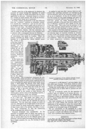
A pump can be designed to run in reverse as a motor, or as a slave unit. The design may follow one of several types, such as the vane, gear, and piston constructions, any of which may be operated by cam or swash-plate. For the most part, pumps al e made of cast iron, although the use of light metals is not unusual. A Swiss patent for pump construction suggests the use of sheet metal, tube or bar plastics, the latter, if necessary, being transparent, so that the functioning of the component can always be seen.
Pressures developed vary considerably. In the operation of machine tools, in which vane pumps ale mostly used, 500 lb. per sq. in. is fairly general. In the case of presses there may be two different pumps and pressures—one for quick traversing and the other, working at higher pressure, for, say, the forming of plastic mouldings.
As applied to road anct other vehicles, there are indi• cations that operating-' preskures 'are ' moving'.in :Mt-upward direction, and on one American tractor 500 lb:: per sq. in. is employed. It may be of interest to meti4 tion that pumps are now being designed and made fat' pressures of between 2,000 lb. and 5,000 lb.per sq. in. Gear-type pumps are being developed for such purposes, although, in the past, they have suffered from loss of efficiency, caused by wear, chiefly on the face of the gear teeth. This arises from the pressure of the fluid, which becomes locked between the teeth at con-,_ tact points, but this drawback is being overcome. .
One essential of the fluid employed is that it must be able to withstand extreme changes of temperature without showing signs of excessive variation in viscosity. In other words, the viscosity index must be high, otherwise there is a considerable variation between cold and hot conditions. 'There are new fluids being developed in which temperature variations, extending from
60 degrees F. to 400 degrees F. and even higher, have little effect upon viscosity. Such fluids, which are called silicones, will undoubtedly be used in hydraulic systems.
Fittings that enable pipes to be connected or disconnected without loss of either fluid or pressure can now be obtained.
The use of hydraulic power for the operation of auxiliary units on vehicles is, of course, not new. A typical example is the operation and adjustment of equipment as fitted to agricultural tractors. As is well known, tipping bodies have been operated in this way for many years.
The mere presence of an hydraulic transmission system on a road vehicle will naturally lead to the application of the principle 'to reduce the manual effort in many directions. Hydraulic suspension, incidentally, is already in an advanced stage of development.
We are undoubtedly on the threshold of a great forward movement in the use of hydraulics, not only to provide a smooth and efficient type of torque converter, but to perform many identical duties.
REFERENCES.
Crossley Motors, Ltd., B.P. 579692, Fluid Flywheel and Engine Braking, Ettore Bugatti, B.P. 11840/45, Fluid Flyw eel. Hugo Lentz, B.P. 1571/1912, Hydrostatic Transmission.