


An Automatic and Infinitely Variable Gear
Page 67
If you've noticed an error in this article please click here to report it so we can fix it.
The Hobbs Transmission, Exhibited at Olympia by the Maudslay Concern, is an Ingenious Adaptation of the Wellknown Impulse Principle
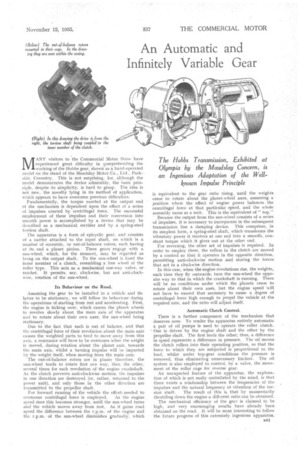
MANY visitors to the Commercial Motor Show have experienced great difficulty in comprehending the working of the Hobbs gear, shown as a hand-operated model on the stand of the Ma:mislay Motor Co., Ltd., Parkside, Coventry. This is not surprising, for, although the model demonstrates the device admirably, the basic principle, despite its simplicity, is hard to grasp. The idea is not new, the novelty lying in its method of application, which appears to have overcome previous difficulties.
Fundamentally, the torque exerted at the output end of the mechanism is dependent upon the effect of a series of impulses created by centrifugal force. The successful employment of these impulses and their conversion into smooth power is accomplished by a device that may be described as a mechanical rectifier and by a spring-steel torsion shaft.
The apparatus is a form of epicyclic gear, and consists of a carrier attached to the input shaft, on which is a number of eccentric, or out-of-balance rotors, each having at its end a planet pinion. These gears engage with a sun-wheel, which, for the moment, may be regarded as being on the output shaft. To the sun-wheel is fixed the inner member of a clutch, resembling a free wheel of the roller type. This acts as a mechanical one-way valve, or ratchet. It permits, say, clockwise, but not anti-clockwise, rotation of the sun-wheel.
Its Behaviour on the Road.
Assuming the gear to be installed in a vehicle and tin latter to be stationary, we will follow its behaviour during the operations of starting from rest and accelerating. First, the engine is ticking over, which causes the planet wheels to revolve slowly about the main axis of the apparatus and to rotate about their own axes, the sun-wheel being stationary.
Due to the fact that each is out of balance, and that the centrifugal force of their revolution about the main axis causes the weighted parts to tend to move away from this axis, a resistance will have to be overcome when the weight is moved, during rotation about the planet axis, towards the main axis, whilst a turning impulse will be imparted by the weight itself, when moving from the main axis.
The out-of-balance rotors are in phase; therefore, the sun-wheel tends to rotate first one way, then the other, several times for each revolution of the engine crankshaft. As the clutch prevents anti-clockwise motion-, the impulses in one direction are destroyed (or, rather, returned to .the power unit), and only those in the other direction are transmitted to the propeller shaft.
For forward running of the vehicle the effortneeded to overcome centrifugal force is employed. As the engine speed rises this becomes stronger, until the sun-wheel turns and the vehicle moves away from rest. As it gains road speed the difference between the r.p.m. of the engine and the r.p.m. of the sun-wheel diminishes gradually, which is equivalent to the gear ratio rising, until the weights cease to rotate about the planet-wheel axes, assuming a position where the effect of engine power balances the centrifugal force at that particular speed, and the whole assembly turns as a unit. This is the equivalent of "top."
Because the output from the sun-wheel consists of a series of impulses, it is necessary to, incorporate in the subsequent transmission line a damping device. This comprises, in its simplest form, a spring-steel shaft, which transforms' the vibratory power it receives at one end into a smooth, constant torque which it gives out at the other end.
For reversing, the other set of impulses is required. In order to employ these, the rollers in the clutch are moved by a control so that it operates in the opposite direction, permitting anti-clockwise motion and storing the forces that act in a clockwise direction.
In this case, when the engine revolutions rise, the weights, each time they fly outwards, turn the sun-wheel the opposite way to that in which the crankshaft is running. There will be no conditions under which the planets cease to rotate about their own axes, but the engine speed 'will not have to exceed that necessary to cause a degree of centrifugal force high enough to propel the vehicle at the required rate, and the ratio will adjust itself.
Automatic Clutch Control.
There is a further component of the mechanism that deserves note. To render the apparatus entirely automatic a pair of oil pumps is used to operate the roller clutch.
• One is driven by the engine shaft and the other by the propeller shaft. The first feeds the other; thus,.a difference in speed represents a difference in pressure. The oil moves the clutch rollers into their operating position, so that the force to which they are subjected is proportional to the load, whilst under top-gear conditions the pressure is removed, thus eliminating unnecessary friction. The oil system is also employed to control, by a valve, the movement of the roller cage for reverse gear.
An unexpected feature of the apparatus, the explanation of which is not easily assimilated by the mind, is that there exists a relationship between the frequencies of the impulses and the natural frequency of vibration of the tor sion shaft. The result of this is that by momentarily throttling down the engine a different ratio can be obtained.
The mechanical efficiency of the gear is claimed to be high, and very encouraging results have already been obtained on the road. It will be most interesting to follow the future progress of this extremely ingenious apparatus.