


OLYMPIAN 7
Page 58
Page 59
Page 60
If you've noticed an error in this article please click here to report it so we can fix it.
,CHNICALITIES
TO anyone who has been trained as an engineer the Commercial Motor Skipw at Olympia is a veritable mine of valuable information. In this review of some of the technical features of certain products we have not delved into the major points of construction, because these can be left to chassis descriptions. Instead, we have endeavoured to draw attention to details which might, perhaps, escape the notice of the more casual observer, or which may not be made apparent by an inspection without an explanation. A technical man on a stand ma it say when asked : "Well, our chassis has been cleaned up and follows what may be termed normal design, but. . . ." In this review we are trying to bring forward some of the "huts," and in no particular order of make or merit.
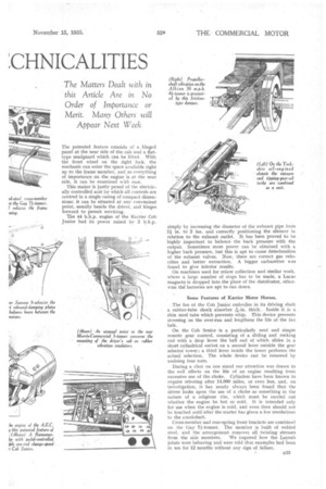
On the Ransomes trolleybus our attention was at once attracted by the small tie rod bridging the fork of each section of the cardan joints. The rods are screwed at their ends and have split-pinned castellated nuts, each nut being but little more than finger tight. The reason for their presence is that under the Stroboscope (an instrument which gives to the eye the effect of arresting machinery although, in fact, this is working) the forks, when the shaft is rotating at a fair speed, can be seen actually to open slightly under the effect of centrifugal force, althougi, they are comparatively massive. This previously caused the bushes to wear oval and permitted side play, but the tie rods obviate the trouble.
A Cause of Commutator Trouble.
It was also found that, with an ordinary propeller shaft in a large-angle transmission, the cyclic variation of speed and shaft whip gave rise to excessive sparking at the commutator, which is now overcome partly by the method already explained and partly by utilizing a thin tube of large diameter for the shaft.
The motor weighs only 11.2 lb. per b.h.p., and with a total weight of 900 lb. has driven a 13-ton double-deck bus for two years with no trouble. The latest motors have casings of welded boiler plate and inspection covers which can be removed without using a spanner. Armature end windings held by wound wire sometimes tend to make the wire slip towards the core under centrifugal force. They are now held down by a welded-steel ring, which is secured to the ventilating fan. Incidentally, the units
B32 are specially designed for rheostatic and regenerative braking. Another neat Ransomes-Garrett device iS an electro-mechanical brake forming a unit consisting of an electric motor bolted to a casing containing a worm gear. On the shaft of the wheel are dogs, and the armature has to turn only far enough to engage the dogs and apply the brake through normal rods. The design of the motor prevents it from burning out, although the armature does not rotate, and the pedal actuating it controls a normal-resistance regulator. The device is perfectly silent in operation.
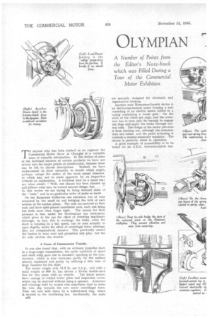
A good example of accessibility is to be found on an A.E.C. forward-control bus. The patented feature consists of a hinged panel at the near side of the cab and a flattype mudguard which can be lifted. With the front wheel on the right lock, the mechanic can enter the space available right up to the frame member, and as everything of importance on the engine is at the near side, it can be, examined with ease.
This maker is justly proud of the electrically controlled unit by which all controls are centred in a single casing of compact dirtier-I:. sions; it can be situated at any convenient point, 'usually beside the driver, and hinges forward to permit servicing.
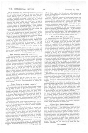
The 44 h.h.p. engine of the Karrier Cob Junior had its power raised by
simply by increasing the diameter of the exhaust pipe from 1i in. to 2 ins, and correctly positioning the silencer in relation to the exhaust outlet. It has been proved to he highly important to balance the back pressure with the output. Sometimes more power can be obtained with a higher back Pressure, but this is apt to cause deterioration of the exhaust valves. Now, there are correct gas velocities and better extraction, A bigger carburetter was found to give inferior results.
On machines used for refuse collection and similar work, where a large number of stops has to be made, a Lucas magneto, is dropped into the place of the distributor, otherwise the batteries are apt to run down.
Some Features of Karrier Motor Horses.
The fan of the Cob. Junior embodies in its driving .shalt
a rubber-tube shock absorber thick.. Inside it is thin steel tube which prevents whip. This device prevents stressing on the over-run and lengthens the rife of the fan belt.
On the Cob Senior is a particularly neat and simple remote gear control, consisting of a sliding and rocking rod with a drop lever the ball end of which slides in a short cylindrical socket on a second lever outside the gear selector tower: a third lever inside the tower performs the actual selection. The whole device can be removed by undoing four nuts.
During a Chat on one stand our attention was drawn to the evil effects on the life of an engine resulting from excessive use of the choke. Cylinders have been known to require reboring after 14,000 miles, or even less, and, on investigation, it has nearly always been found that the driver looks upon the use of a choke as something in the nature of a religious rite, which must be carried out whether the engine be hot or cold. It is intended only for use when the engine is cold, and even then should not be touched anti' after the starter has given a few revolutions to the crankshaft.
Cross-member and rear-spring front brackets are combined on the Guy 4-tormer. The member is built of welded steel, and the arrangement removes all twisting stresses from the side members: -We inquired how the Layrub joints were behaving and were told that examples had been in Use for 12 months without any Sign of failure:
On the six-wheeler is a particularly neat arrangement of the rear suspension, which gives 25 per cent. more load , on the driving wheels, the springs for these having a smaller deflection per ton. The balance gear has to be arranged accordingly by giving a ratio of 5 to 4 on the lever arms, whilst to spread the braking effort the Lockheed cylinders for the bogie rear wheels are / in. less in diameter than those for the drivers. Bell-cranks on the lever arms make contact with rubber cushions when the vehicle is braking or climbing gradients. When climbing, the rear of each of the forward springs goes down and releases the load on the corresponding rear spring, the transfer being limited by the rubber buffers.
Another Guy feature of interest is the low-pressure doubleplate clutch, the load on the facings being only .7 lb. per sq. in. In addition, the clutch is cleverly arranged to permit the use of an outboard .bearing, so that the spinner plates are between ball bearings 10 ins. apart.
Noteworthy frame bracing is to be found on the Dodge 4-tonner, in which an additional channel member runs inside each of the main channels from the front-spring
forward shackles to just aft of the gearbox. The to braces, which are holed for lightness, are then inswept to the cross-member carrying the centre bearing of the propeller shaft:.
.. The hand brake now operates on all four wheels, and there is a neat steering bracket constructed in halves and having three holes for two bolts, so that the position ot the steering wheel can be altered by some 2 ins.
Some Interesting Thornycroft Characteristics.
The Thornycroft Z.E,T.C.4 in chassis form with 'a body length of 17 ft. and 34-in. by 7-in. tyres (single and twin) weighs only 2 tons 1 cwt. Part of its strength is derived from pressed-steel box-section cross-members. Even the maximum-load two-axled chassis weighs only 3 tons 7/ cwt. with its Thornycroft 85 b.h.p. oil engine. This new unit uses the Ricardo Comet head, giving speeds up to 2,200 r.p.m., and the remarkable consumption (for an antechamber type) of .37 pt. per b.h.p. In this and other Thornycroft products the arrangement of the 'spring holding-down bolts, although fairly well known to most of our readers, is particularly worthy of mention. The bolts are set at an angle and practically line contact is afforded so that the spring is not held rigidly and the bolts are not stressed individually.
An unusual fitting on the Albion 30 m.p.h. 4à-ton Model 127 is a torsion damper of the friction-flywheel type mounted on the propeller shaft immediately in front of its centre bearing.
• Engine Details on the Dennis Lancet II.
One always expects to find points of novelty and interest on Dennis products, and we were not disappointed. Attention to detail is shown in he fan, the boss of which is provided with three keys, which drive the water, pump through the medium of cast-iron radial dogs ; if the water freee,es the dogs break off. .The dog member is keyed on to the pump shaft and held by a Circlip so that it can be replaced with little difficulty. The fan-driving pulley reminded is of our early motorcycling days, for it is of the split type with the outer flange screwed on to the boss of the inner. - Another neat fitting is the stirrup by which the exhaust pipe is held to the manifold. Tightening is effected by a. setscrew in the stirrup ; this is treated to prevent corrosion under the effects of heat.
A two-plate clutch held up to its work by a stout coil spring is utilized to drive the 8-in, dynamo. The outer part of this clutch has serrations, the dynamo speed is in a ratio of 1.5 to 1 engine speed, and each serration represents 1/ degree. The timing gear is at the back of the engine, and in the case is an inspection hole for the fuel. pump driving wheel, the movement 'of one tooth of which represents 7.5 degrees. An indicating arrow for the serrations assists in timing.
Suction for the brakes is obtained from a gear 'pump driven in line with the:oil-fhel 'pump. It has an oil seal, and the discharge of air and oil is taken to the sump. Up to 24 ins. of vacuum dim be obtained at idling speed. On
B34 all the large engines the big-ends are split obliquely to permit the witlielrawal of the pistons and rods through the tops of the cylinders.
Another interesting example of cross-frame bracing was found on a T.S.M. chassis. This is built of angle-steel members bolted together at the centre, and additionally strengthened at this point by a rectangular plate. One brace is situated above the propeller shaft and the construction is duplicated. below the shaft.
Neatness is carried to a high degree on the latest Daimler chassis, as is exemplified by the wire conduits formed integrally with the cast-aluminium dash. At the entrances these are protected by rubber bushes and there are rubberized-canvas protectors inside, The conduits stretch right across the dash from the dynamo to the switchboard and down to the control box for the dynamo cut-out, etc.
A Remarkable Oil-engine Control Unit.
A unique control unit was discovered on an ArmstrongSaurer. oil engine, for use in conjunction with the fuel pump. It is of the hydraulic type and performs five distinct functions. For high-speed work there is of necessity a number of variables to be controlled to give complete combustion, combined with lo' consumption, satisfactory output and smoke-free exhaust. In the ordinary course the driver controls the tinting of injection and the amount of fuel, but he may, on a hill, depress the accelerator excessively and thus cause too much fuel to be injected. resulting in smoke. It is therefore considered essential by. this maker to effect the control automatically and thus ensure good running under all variations of load and speed. The end of the injector-pump shaft is extended to drive a gear-type oil pump with two leads ; one delivers fuel under a pressnre of two to three atmospheres into the, injector pump, thus eliminating any danger of air bubbles; the other lead passes to the separate hydraulic-control unit. This limits the idling speed and the maximum speed, which, in the P.D. engine, is 3,000 r.p.m. It controls the advance and retard mechanism for fuel delivery, and, incidentally, this is now in the engine-timing case where it can be of mucli more suitable dimensions than when it was in the pump ; it also limits the feel quantity relativelyto the engine load.
Improvements have also been made in the type of injector. This is no longer of the multi-hole pattern, hut with a mushroom-type head giving a film spray from the circular orifice. The oil is emitted as a fine fog like a flat umbrella or disc. Dribble is impossible and squirting of the fuel is avoided.
The fuel lead to the injector is most ingenious. The connection -ends in a ball head in which, are the necessary holes. The top of the injector has a conical seat for the ball, which is held down on to the injector by a plug with a similar seat, so that this one plug serves the functions of making the connection and securing the injector. It is interesting to find that no leak-off is required.
The need for automatic control is also recognized in the latest Leyland small oil engine, which embodies a C.A.V.-Bosch. vacuum governor of 'the spring-controlled diaphragm type, the vacuum for which is obtained from the air inlet above the cylinders, where is situated a throttle valve. This new engine has its spherical ante-chambers machined from the solid 'castings of the cylinders and head, instead of use being made of inserted pots.
A Few of Many Bedford Improvements.
The new Clayton-Dewandre progressive vacuum servo is
used on the Bedford. The release valve on this gives much smoother action than in the old pattern. A. refinement on the flexible tubes carrying the brake cables is a small tubular oil lead reaching from a Tecalemit lubricator carried on the frame-bracket anchorage of each brake tube. This permits a more solid push than when the lubricator is carried direct on the metallic tubing. The brake-rod -antirattling device consists of small frame brackets, each of which has a large hole carrying a collar piece on which is a floating washer held against the face of the braelset by a
spring. The rod can thus float in the large hole, but vibration is damped.