


HINTS ON MAINTENANCE.
Page 32
Page 33
If you've noticed an error in this article please click here to report it so we can fix it.
How to Get the Best Out of a Vehicle, to Secure Reliability and to Avoid Trouble.
CONTRIBUTIONS are invited for tl-is page from tied managers, drivers, garage foremen, and mechanics, works staff and draughtsmen, and will be paid for on a generous scale. Every system, make, and type of commercial motor vehicle will be dealt with, and the matter should be written with a view to the disclosure of Workshop and garage practice in the maintenance of a vehicle—practices which, whilst they may be quite normal, are peculiar to the particular vehicle and may not be generally known to those responsible for its running. Expedients and suggestions for overcoming roadside and other troubles are covered in the tollowing page, headed "Roadside and Garage!' Communications should be addressed to "The Editor, The Commercial Motor, 7-15, Rosebery Avenue, London, La. 1."
117.—Adjusting Roller Bearings on P-type Halley.
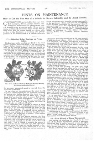
Tiinken taper roller bearings are fitted to the road wheels, gearbox, and worm shaft of the six-cylinder, P-type Halley chassis, and it is most essential, if they are to function properly, that they should be correctly lubricated and kept in accurate adjustment. Aa regards the front wheels, if excessive play is present, the hubcaps should be unscrewed and, inside them, on the end of each pivot arm, will be found a slotted nut locked by a split pin ; the latter should be withdrawn. By tightening up the nut, the wear on the bearing can be taken up if, at the same time, the necessary amount of metal is removed from the inner face of the nut.
In carrying out the adjustment the wheel should be jacked off the ground and the pivot nut tightened up against the washer, keeping the inner cone of the bearing in position until the wheel beds. While doing this, revolve the wheel to ensure that all the working surfaces come into contact. After tightening up the nut, unscrew it between one-sixfh and one-third of a turn, in order to allow the wheel to rotate freely, but without side play.
This adjustment can be tested by taking a short bar and placing the end of it between the tyre and the floor, at the same time holding one finger on the cage of the bearing. By moving the bar up and down, excessive wear or looseness can be detected. When a very slightsrock is felt and the wheel oscillates freely, the adjustment is correct. Now replace the cotter and the hub cap.
In the case of the rear wheels, unscrew the Ross Jock nuts which hold the driving cap in contact with the wheel, and on withdrawing this cap a special nut will belfound screwed on to the end of the back aide tube. This is locked in position by means of two small tee-headed bolts and nuts, and after withdrawing these the large nut can be screwed up furtiler by filing a small amount off the end of the rear axle tube. Testing for side play and correctness of adjustment should be carried out in the same manner as with the front wheels. After the adjustment has been completed, the locking bolts should be put back through the two pairs of holes in the nut and in the end of the back axle tube, after which, replace and firmly secure the driving cap. If too much end play has developed in the worm shaft, this can be taken up by removal of the foot brake drum and the outer dust cap cover, when a locking nut will be found on the worm shaft. After removing the set-pin holding this in position, the locking nut should be rotated by means of a tommy
bar and the end play taken up, except for a, small amount (between .016 in. and .020 in.), whisk can be effected by tightening the nut up completely and then backing it about half a turn. Care should
be taken that the universal fork on the front of the worm shaft is bearing tightly against the inner cone of the forward bearing.
Dealing with the gearbox, the first and third motion shaft bearings are taken up by reducing the length of the sleeve between the inner cones and
tightening up the locking nuts on the shafts. In the case of the layshaft the thickness of the distance
washer between the end of the shaft and the inner cones will require to be varied if the necessary adjustment necessary k here cannot be obtained by in creasing the thickness of the joint between the flange of the bearing housing and the face of the gearbox. If it is necessary to fit new bearings, it is found that the best allowance for fitting the cups in their housings is from .0015 in. to .0035 in. press fit for
cups 2i ins. to af ins, diameter, and .003 to .005 in. on cups of 4 ins. to 7 ins. diameter. For the -cones mounted on stationary spindles there should be provided a free fit., the best being .005 in., so that the cone will tend gradually to creep in service and thus distribute the wear.
It is essential that cups be mounted securely against their seats, and care should be taken to ensure that they are not canted in their mountings. If it is necessary to fit two new cups to a hub or housing, great care should be taken to ensure that these are forced home parallel with one another, preferably by means of a self-aligning fixture. For cones on a rotating shaft a press fit is desirable for gearbox work. In the case of the worm shaft; the cones should he' made a very light creep fit in order to permit of ease in adjustment.
Lubrication of the road wheel bearings should be very carefully attended to, a small quantity of oil being given each day. Correct adjustment and lubrication will ensure good service.
I18.—Rear Wheels of J-type Thornycroft.
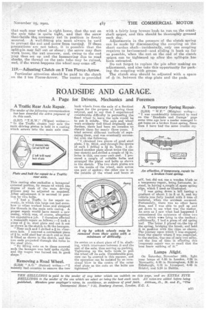
The method of attaching the wheels to the rear axle of the J'-type Thprnycroft vehicle is excellent., providing that a certain amount of care is taken, and the wheels should be examined periodically to make certain that there is not too much end play.
Whilst performing this examination, make certain
that each rear wheel is right home, that the nut on the axle tube is quite tight, and that the screw that Iholds the necessary nut in position is firmly secured. A well-fitting pin must always be used to prevent the nut and screw from turning. If these precautions are not taken, it is possible that the split-pin may fall out or shear ; the screw may then work loose; the nut unscrew, and, owing to the end play thus set up and the hammering due to road shocks, the thread on the axle tube may be ruined, and, if the worst happens the wheel may come off.
119.—Adjusting Clutch on 2 Ton Pierce-Arrow.
Particular attention should be paid to the clutch on the 2 ton Pierce-Arrow. The centre is provided with a fairly long bronze bush to run on the crankshaft spigot, and this should be thoroughly greased each day. Adjustments in the pressure of the clutch spring can be made by disconnecting the coupling on the short cardan shaft—incidentally, only one coupling requires to belloosened—and sliding it back as far as possible, when "the nut on the end of the clutch spigot can be tightenedup after the split-pin has been extracted.
Do not forget to replace the pin after making an adjustment, and also take this opportunity. for packing the coupling with grease. The clutch stop should be adjusted with a space of15,-, in. between the stop plate and the pads.