


PATENTS SUMMARIZED.
Page 24
If you've noticed an error in this article please click here to report it so we can fix it.
Detachable Wheels for Allchin Steam Wagons.
With the use of rubber tyres on steam wagons becoming more and more general, the necessity for detachable wheels which can be removed quickly for tyre renewals and as quickly replaced, becomes more apparent. William Allchin, Ltd., of Globe Works, Northampton. a company which is well-known to Our readers as a maker of steam wagons, has, in company with others, patented an arrangement of detachable wheels and brake gear for steam wagon chassis which has several good points, not the least commendable of which is its simplicity—a most desirable feature.
The axle is constructed in the manner common to most steamers, that is to say, the main through shaft, which drives one of the wheels, is coupled to one sun wheel of the differential gear, the other wheel being driven off the other sun wheel by means of a sleeve which is free to revolve upon the main shaft. In the Allchin design a spider is formed upon this sleeve; the spider carries two suitable proportional bosses, through which • a couple of bolts pass. The nave of the svheel is constructed to receive these bolts, and by taking off the nuts on the outer ends of the bolts the wheel is rendered instantly removable. For the other wheel a false sleeve, similar in exterior dimensions to the loose one, and having formed integral with it a spider of the same kind; is keyed to the main shaft. The wheels are thus made interchangeable. A particular feature of the invention is the arrangement of the brake drams. These are flanged inwardly, and bolted to the spiders to which the wheels are attached. It is thus possible to withdraw and change or replace the wheels without in any way disturbing the brakes.
Reference is made in the specification to several details of construction, most of which can be discovered by the reader on reference to the drawing which we reproduce. We -would, however, direct attention to the design of the bolts which secure the wheels in place. They are tightened up, as may be seen, on taper heads, in consequence of which there is no tendency for them to work loose, or for play to develop between them and the holes in which they bear.
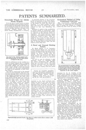
A Novel and Unusual Braking System.
M. Emile Massis, of 17, Lancaster Court, Newman Street, W.,. has devised a novel braking system, the most unusual feature of which is that the brake shoes operate by direct contact with the ground. They are carried at the end of trunk pistons and lowered into direct contact with the ground by hydraulic means.
As will be seen by refesence to ,slise drawings which we -reproduce from the patent specification (No. 109,125), there are two shoes which, with their hydraulic operating gear, are suspended from the rear axle. A pull on the wire which is shown leading from the piston
depicted on the detail sectional view, causes the fluid to flow into the hollow plunger which is attached to the shoe, thus depressing the latter andforcing it into close contact with the ground. The wire may be operated in the customary manner by means of a hand lever, or, alternatively, it may be connected to the steering gear, so that the brakes come into action when the steering is sharply deflected. In this manner it is claimed by the inventor that it acts as a preventive of skids when travelling over greasy surfaces. •
Economical Method of Using Compressed Coal-Gas.
The impracticable suggestion that cylinders of compressed air should be used to propel the engines of a motor vehicle has been made by many ; it has
remained for H. E. Freakly, of 25, Lovett Street, Salford, to suggest a combined compressed gas and internal-oornbustion-engined power unit for particular application to a einnmercial vehicle.
In his patent specification, which is numbered 109,821, he describes an arrangement in which a small engine,' either f the rotary or reciprocating type; takes the place of the reducing valve in a vehicle which carries as its fuel supply reaervoirs of compressed gas. The gas Passes from the storage cylinders to the first engine, which it 'drives, doing Work in the course of its reduction of pressure from that at which it is stored to one snore nearly approaching the atmospheric. It exhausts from this engine into a second storage cylinder, whence it is taken in the ordinary way to the induction pipe of the internal-combustion engine, where it is mixed with the necessary proportion of air, drawn into the cylinders, explodes, and performs further work in the usual manner.
A suggested arrangement of the various components is shown in the accompanying drawing, in which the compressed gas engine is shown immediately behind the flywheel of the internal-combustion one, and operating on the same shaft. Suitable provision is made for heating the gas in the various stages of its passage from the initial reservoir to the internal-combustion engine.
In view of the °increasing attention being focussed upon the coal-gas issue, this method of using compressed gas may create some interest.