


Progress in Pneumatic Suspension
Page 36
If you've noticed an error in this article please click here to report it so we can fix it.
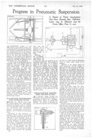
ASUSPENSION system, if soft enough to give smooth riding, may sometimes tend to be laterally unstable,. and usually a compromise between the two requirements ',has to be adopted. To increase smoothness of riding, without at the same time decreasing the ctahility, is the obje6t of an improved pneumatic suspension scheme shown in patent No. 543,837 by Firestone Tyre: and Rubber Co., Ltd., Brentford.
A back axle of conventional type is equipped With two torque rods (I) which are anchored to the frame at
their forward ends. The rods have pivotal connections at both ends, rubber bushes being employed," The resilient suspension elements are a pair of deformable rubber bellows (2) interposed between the torque rods and the frame. These are piped to a common air reservoir of certain volume, and transference of air from bellows to reservoir is controlled by a valve having definite flow characteristics.
To preserve lateral stability, recourse is taken to a rod -(4) which lies across the frame 'hi a sloping position. One end (3) is attached to a frame bracket; whilst.the other (5) is cakried on a projection from the axle casing. In each case a rubber bushing is. used, the bushes being flanged to give a slight uuiversal aation, whilst retaining a general rigid control.
TO FACILITATE GEAR-CHANGING WITH HYDRAULIC CLUTCH DATENT No. 543,713 comes from .I. Leyland Motors Ltd., Ham Works, Kingston-on-Thames, and V. Pilkington, and describes some. of the difficulties encountered with transmission systems incorporating hydraulic clutches, and a scheme for overcoming theist.
According to the, patentees, an hydraulic clutch, used in conjunction with a gearbox, sometimes gives rise to difficulty in gear changing, owing to the driven part of the hydraulic unit resisting alteration of speed, because of its mass. Synchromesh mechanisms are, of course, employed, but the wear on their friction clutches has been found to be considerable. The proposed remedy is to provide an additional clutch between the hydraulic unit and the gearbox, and to operate it automatically when a 'gear change is 'made.
Referring t o the accompanying diagram, the fluid device (7)
is connected with the gearbox by an additional clutch (8). The method of operating this clutch is as follows: Shaft 4 is coupled to a suctionactuated servo cylinder (3) for normal use, and, as a safeguard, to an emergency pedal (6) which, when not required, can be " folded " out of the way. The Servo control valve (2) is operated electrically, the switch for it being placed on the end of the gear-lever (1). When the last-named is gripped by the driver, the eventual result is to free the gearbox from the hydraulic clutch in readiness for a. change, It is also proposed, automatically, to reduce engine speed, particularly during .up-changes, and to this end an electric control (5) is provided for .opera.tion of the rack-rod of the injection pump.
DOUBLE-FUNCTION INJECTOR • WITH TWO SETS OF JETS A N injection nozzle having two ti orifices giving different degrees of atomization is shown by G. Kammer, High Austhy, Ilkley, in patent No. 543,795. The device is intended for use with pilot injection and is arranged so that the initial spurt is discharged from an' orifice more suited to its purpose.
Selection of the proper orifice for each component of the charge is governed by the pressure of the fuel. The nozzle of the injector has one set of orifices (8) supplied by a central bore from the space (9), whilst another set (7) receives its fuel froth a passage (5). The pump, of the jerk type, is connected to the inlet (I), an extension of which contains a sliding valve (2). When the charge arriVeS, it first`thoves the valve (2) to the left(against a spring) "until the port, at -the end of passage 5, is uncovered by a cross-bore
(3) in the slider. • ' .
Fuel then' flows from' the inlet, through the bore in valve 2, and is nItimateIy' sprayed from the -jets (7). The jets are fine enough to allow the pressure to rise as more 'hid arrives, and the valve -(2) iS then moved farther to the left. Port 3 in the slider moves away from the mouth of passage 5 and the fuel is thus diverted via cross-bore 4 into space 9, which, as previously mentioned, leads to the second set (8) of spray holes.
Another feature of the invention is that the jets (7 and 8) are open only when the fuel pressure is present. This is broaght about by the use of a semirotary sleeve-valve (6), which is rocked by a small crankpin -(10) engaging with a notch in the sliding valve (2).
The axis of the valve plunger (2) is off-set in relation to that of the semirotary sleeve (6), so the relative positioning of these two parts is quite convenient for the transference of motion from the one to the other in the manner outlined. It is claimed that the tendency to coke formation around the orifices is reduced and that cleaning of the nozzle is facilitated, without the risk of damage to delicate parts.