


Patents Completed.
Page 26
If you've noticed an error in this article please click here to report it so we can fix it.
complete specifications of the following patents will be sent to any address in the United Kingdom by the Sales Branch, Patent Office, Holborn, W.C., upon receipt of eightpence per copy.
A Novel Speed Control.
S. K. Evans, No. 20.730, dated 11th September, 1912.—The speed of a motor vehicle is controlled by means of electric contacts arranged on the speedometer dial. One contact is placed at the maximum speed allowed ; the pointer of the speedometer being used for the other contact. The circuit thus completed is arranged to control the vehicle in a manner depending upon the type of vehicle. Thus, for instance, with an internal-combustion engine this may be arranged to cut out the ignition, or with an electric drive the power circuit of the car would be directly controlled. Special arrangements are provided to prevent this control being tampered with. The adjustable contact on the speedometer dial is only accessible when the cover of the instrument is removed, and this cover is provided with a lock and key. In order to prevent the speedometer being disengaged from the running wheels, a key. locked coupling is employed to prevent the transmission gear-wheels being taken out of engagement with one another.
A Rotary Mushroom Valve, C. Tuckfield, W. G. de F. Garland and W. Petersen, No. 9736, dated 24th April, 1912.—In order to render the action of
valves more sure, and to prevent them sticking or fouling, a rotary motion is imparted to the valve as it is moved up and down off its seat. This motion is obtained by cutting spiral grooves round the stem, and in the sleeve in which the stem works. A number of balls are , placed in the groove, to act as a thread in order to give the valve a rotary motion. Cooling System.
B. E. D. Kilburn (Sulzer Bros.), No. 25.219, dated 4th November, 1912.—It is an advantage to be able to carry the smallest quantity of cooling water on a vehicle propelled by internal-combustion engines. If more than one engine is used, it is desirable to be able to arrange the circulating system of the cooling water
in various ways according to the conditions of use. The illustration shows a locomotive in which the larger engine at the left-hand end is for driving, and the smaller engine at the right-hand end operates the pumps, brakes, electric light, and other accessories. The piping for the circulating water is so arranged, that the water can be made to flow through both cylinders of the main engine and of the auxiliary engine in series.
A Paraffin Gas Producer.
A. W. Southev, No. 21,363, dated 27th September, 1911.—This specification describes means of using petroleum oil as a fuel for internal-combustion engines. The general process comprises the vaporizing of a portion of the fuel, and heating it to such a temperature that it becomes a permanent gas. The accompanying drawing shows one form of apparatus suitable for this purpose. A float-feed tank on the left-hand side controls the supply of oil to a wick, and the flame obtained is passed up between conical baffles, so as to heat a coned spiral tube, through which the main flow of oil takes place. This oil is vaporized in the tube and delivered near the centre a the vesse , inside the flame from the wick. The vapour passes out through the flame and mixes with the requisite quantity of air admitted at each side, and is drawn off by a central tube to the engine.
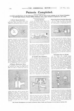
Preparing Road-making Material.
R. J. Wright, No. 6636, dated 17th September, 1912.—Bituminous material for road-making is manufactured in a
portable apparatus by passing stone or slag through a tank of hot or boiling water, then drying it and finally depcsitbing it in a mixing tank, containing hot tar. In the arrangement illustrated, the stone or slag is delivered into the hopper shown at the left-hand side. It is then carried by a conveyor, which is fitted v,ith mixing paddles, up towards the right, and the stone is heated to the required temperature in its passage. It is then delivered into a drying conveyor, which is preferably arranged within a perforated casing, so that the air has free access to it.
Changing Gear by Pedal.
C. B. Lines, No. 13,598, dated 10th June, 1912.—In order to facilitate the operation of changing the gear of a motor vehicle, the change-speed lever and the clutch are combined. The arrangement is that the clutch lever is moved in one direction to engage and disengage the clutch, and is moved in another direction to make the necessary operations in the gearbox. In the construction illustrated, the clutch lever is guided in a framework. and is pushed down in the ordinary way for operating the clutch. When it reaches the end of its travel, an open part of the framework is reached, so that the lever can be moved transversely in either direction. This movement brings the various gears into operation, and when they are in engagement the clutch pedal is Lowed to rise. It will thus he seen that the operation of this single pedal, first of all declutches the engine, then brings the gear into mesh, and finally lets the clutch in again.