


Injection-pump Progress
Page 60
If you've noticed an error in this article please click here to report it so we can fix it.
A Résumé of Recently Published Patent Specifications
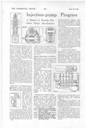
THE necessity of avoiding the formation of a partial vacuum in the suction side of an injection pump is stressed in patent No. 409,125, by Rudolf L'Orange, Satfierstrasse 25, Stuttgart, Germany, and Simms Motor Units, Ltd., Percy Buildings, Gresse Street. London, W.1. The pump described possesses certain improvements intended to ensure absence of back pressure and dribble.
Referring to the drawing, fuel enters under pressure through passages (7, 3, 4, 6 and 5) into the internal bore (8) of the pltinger, after which it passes the spring-loaded valve (10) and arrives at the compression space (11). Upon the rising of the plunger, injection takes place out of the upper end until such time as the pressure is relieved by the uncovering of helically adjustable controlling edges (9), after which the excess fuel is spilled, via passages (1 and 2), back into the supply side of the pump. The specification stresses the point that there can be no interference betw,en the spilled fuel and that in the suction passage (8), the two paths being entirely separate.
"Safety First " for Hydraulic Brakes.
BRAICING systems using hydraulic pressure are open to the objection that should one of the conduits be damaged, either by accident or by wear and tear, the pressure of the whole sys. tern may be lost by one serious leak. To overcome this defect is the object of patent No. 409,169, by L. and , M. Friedmann, 6, Am Tabor, Vienna, Austria.
The illustration shows one of several ways of carrying the scheme into effect. Included in the pressure line is an Sshaped tube having a loose ball (3) in the bottom end. The operating liquid is supplied under pressure to the end (1) and normally moves the ball only
B46 a little, owing to the small quantity re quired to work the brakes. In the event of serious leakage, however, the ball would be carried along the piping and finally come to rest in the seating (2), thus effectively isolating the leaking conduit.
Improved Supercharger Arrangements.
NEW ideas in the layout of modern compression-ignition engines form the subject of patent No 408,945, by J. L. Jameson, " Elland," Hemingford Road, Cheam, Surrey, the object being to provide a design having compactness coupled with efficient cooling of the supercharger.
The drawing shows an engine having two supercharger housings (1 and 3) cast integrally with the cylinder block. The drive is by bevel gears from the crankshaft, the valve gear being driven by bevels on an extension of the supercharger spindle (2). Water passages around the superchargers are clearly shown. Apart from the novelty of the invention, the drawing is highly informative in respect of the modern tendency in vehicle engine design.
Developments in Magneto Design.
FROM the well-known concern cif Joseph Lucas, Ltd., Great King Street, Birmingham, coupled with the names of E. A. Watson, M.Sc., and F. J. Marlow, comes patent No. 409,007, describing a form of four
spark-per-revolution magneto which has advantages in manufacture, assembly and easy dismantling. In addition, it is claimed that the magnetic flux is more evenly distributed throughout the rotor.
In this design the magnets are made in the form of rings (1 and 2), one of which is made large enough for the rotor to pass through it, thus making for ease of assembly. These magnets are magnetised so as to have their poles at the top and bottom, and are in contact with pole pieces (3 and 4) which extend towards one another and carry the flux into the path of the rotor.
In this type of magneto, the primary and secondary windings are carried by a separate iron circuit placed at right angles to the permanent magnet system, the rotor itself consisting entirely of a laminated iron mass.
A Novel Ignition System.
INTENDED to expedite the starting of heavy oil engines is a system described by E. L. R. Lysholm, Norr Ilalarstrancl 60, Stockholm, Sweden, in patent No. 409,335. The device consists of two elements, a battery-driven motor-generator delivering alternating current, and a step-up transformer. The stepped-up voltage is not applied
directly to the sparking plugs, but is discharged across a tuned circuit to which the plugs are inductively coupled.. According to the inventor, this scheme produces a flaming arc at the plug points, which effectively preheats the charge and overcomes many of the difficulties associated with the starting of this type of engine.
The specification states that the system should produce a pressure of between 10,000 and 20,000 volts, which is approximately equal to that given by an ordinary magneto. With a magneto, however, the current flowing is infinitesimal, whereas this system demands from to 5 amperes at this high pressure.