


An Improved Six-wheeler with side engine
Page 39
Page 40
If you've noticed an error in this article please click here to report it so we can fix it.
Important Modifications Made in the Light of 10 Months' Operating Experience with the First "Northern General" Experimental Bus Chassis
THE Northern General Transport to., Ltd., Queen Street, Bensharn, Co. Durham, has now put into production a number of six-mi.lieeled side-engined passenger chassis. The first experimental bus of this type was described in our issue dated September 1, 1933, and, since August of last year, the vehicle has covered nearly 70,000 miles under service conditions. Experience has suggested improvements that arc now embodied in the new design,
d the latest chassis is known as the SE-6 type.
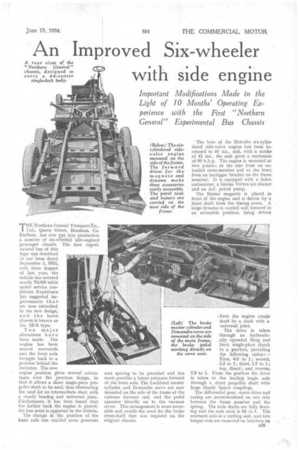
Two major alterations have been made. The engine has been moved rearwards and the front axle brought back to a position behind the entrance. The new engine position gives several advantages over the previous design, in that it allows a short single-piece propeller shaft to be used, thus eliminating the need for an intermediate shaft with a steady bearing and universal joint. Furthermore, it has been found that the farther back the engine is placed, the less noise is apparent in the vehicle.
The change in the position of the fiont axle has enabled more generous seat spacing to be provided and has made possible a better entrance forward of the front axle. The Lockheed master cylinder and Dewandre servo are now mounted on the side of the frame at the extreme forward end, and the pedal operates directly on to the vacuum servo. This arrangement is more accessible and avoids the need for the brake cross-shalt that was required on the original chassis. The bore of the Hercules six-cylindered side-valve engine has been increased to 4i ins., and, with a stroke of 4i ins., the unit gives a maximum of 90 b.h.p. The engine is mounted at two points ; at the rear from an extended cross-member and at the front from an outrigger bracket on the frame member. It is equipped with a Solex carburetter, a Simms Vortex air cleaner and an A.C. petrol pump.
The Simms Lttagneto is •placed in front of the. engine and is driven by a short shaft from the timing cover. A large dynamo is carried well forward in an accessible position, being driven from the engine crankshaft by a shaft with a universal joint.
The drive • is taken through an hydraulic...ally operated Borg and Beek single-plate clutch to a gearbox, providing the following ratios:— First, 6.3 to 1; second, 3.2 to 1; third, 1.7 to 1; top, direct ; and reverse, 7.9 to 1. From the gearbox the drive is taken to the leading bogie axle through a short propeller shaft with large Hardy Spicer couplings.
The differential gear, worm drive and casing are accommodated on one side between the frame member and the spring. The axle shafts are fully floating and the axle ratio is .61 to 1. The rearmost axle is a trailing unit; and two torque rods are mounted on brackets on
the servo unit. the axle casing. Both driving and trailing axles, together with the spring anchorage and brake brackets, are of welded construction.
The frame members are parallel and are slightly arched over the axles, being dropped slightly at the forward end, where the entrance is accommodated. A cruciform member in the centre section supplements the robust cross-members, which are extended to serve as body-support outriggers, as well as providing anchorages for the springs.
A massive box cross-member, midway between the rear axles, carries on its extremities the spring compensating beams. The spring for the rearmost axle is carried above it and is shackled to the forward end of the compensating beam. The leading axle has the spring unclerslung and shackled to the rear end of the compensating beam.
This arrangement has given excellent results and an additional leaf in each of the off-side springs has proved sufficient to compensate for the weight of the engine and gearbox unit.
The foot brake operates on all six wheels and is applied through the Lockheed system, assisted by a Dewandre servo. On the four rear wheels the Lockheed cylinders are carried on the spring brackets, and, through lever=, operate aluminium shoes 6 ins. wide. Drums of 17-in, diameter are used.
The radiator, mounted at the front, comprises a double row of Clayton Still tubes. No fan is required.
Movement is transmitted from the ball-type lever to the gearbox. through a selector box and a long shaft, equipped with two universal joints and mounted on a bearing at the rear end. The accelerator and ignition controls are operated through small-diameter rods, working in armoured cable casing.
The chassis has a wheelbase of 16 ft. 4* ins., and the track is 6 ft. 71 ins., the weight, complete with dynamo, starter, battery and all equipment, being 3 tons 17 cwt. 2 qrs.
Single-deck bodies for this interesting chassis are being built by Short Brothers (Rochester and Bedford), Ltd., Rochester, and 44 passengers can be accommodated With all seats facing forward.