


TWO-WHEELED TRAILER DESIGN..
Page 28
If you've noticed an error in this article please click here to report it so we can fix it.
• A Resume of Recently Published Patents.
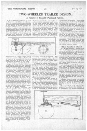
It is not without significance, in view of the recent introelurtion of a Britishmade-six-wheeled vehicle; that attention is now seriously being-.paid, by inventors to the design of trailers suitable for -.Operation with tractors, ac that the two Machines togethea' will form trone sixwheeled motor Vehicle on the same lines as the Scaanmell tractor-lorry. This week there were two such patents. In one of them, No 142,293, by W. C. Bolton, the king-pin which unites the two portions
• sf the complete machines is 'secured to the lower end of a screw, at the top 'of whieh is a ratchet andlever, by the aid of which it is removecbfrom its • place Waco the Jraiter. is required . to be de tached,from the tractor, or vice versa..
It is.'zief course, essentiak; if theaao vantages of the six-whe,eled vehicleare. to be enjoyed to -the:tfull. that a iu-rnberofVthe two-wheeled trallers.is 'keptierriplayed, attninimum of three behtg usually necessary, one of which is attached to the tractor, and presumably, '„engaged in . travelling between: two . terminal points, a Second is inlprocess of being loaded atecine!•of those terminals, and the third is being unloaded at the other. For this to be possible, or, more strictly speaking, convenient, the means of detaching Op trailer floral the tractor, and for sustaining it. in ,a position of equilibrium, notwithstanding its comparatively limited number of wheels, must. be simple in construction and-easily applied; It is tothat end that the two patents under review are Prineipally directed.
In W. • Bolton's invention, the trailer'is Iprovided. With a pair of legs close to thea..frons ,end, and they are ningeif to the frame so that they may he let-down intoa vertical poktion, in Niihich they serve,as a support for the trailer; or they may. be tucked up in a. horizon tal. position underneath the frame. A plain bracket on the trailer is' bored to receive thetking-pin, to which we have abeady referred, and ariathe upper surface the huleris bellIniouthed so as to act as a guide for the king-pin in the extremely -likely event of the litter not being precisely above the hole when engagement is desired. The lower end of the king-pin is hemispherical,and on the rear axle of the traitor is fiiecla bracket situated precisely under the hate in the bracket on the tractor Jar the reception of the king-pin. • The former bracket carries a stud with a bowl-shaped or concave .:hemispherical top, adapted to receive the lower end of the king-phi. Between -the stud and its bracket is inter posed a ball..thrust beving.. • In -tht ordinary position of the king-pin, whei
B501 the tractor and trailer are coupled together, . and ,the connection made secure by the usual forked bar, sliding into suitable grooves cn the, king-pin, the lower end of the latter is clear of the stud On the tractor axle. To uncouple, thejorked bar is first .withdrawn. The lever at the top of the screw to which the 'king-pin is attached is then manipulated to_lower the king-pin on to the
stud. Arrived there, a little further• movement of the screw lifts the trailer, and supports ifs front end, allowing the legs of the trailer to be lowered. Thescrew is then turned ,the other way until the king-pin is entirely withdrawn, so as to be quite clear of the tractor, when the latter can be-driven away.
To couple up tractor and trailer, the former is first driven into place with the hole for the king-pin approximately below it. The screw is then manipulated until the weight of the trailer is taken by the bottom of the king-pin resting on the stud on the axle of the tractor. The legs of tthe trailer' may then be folded. up Out of the way, and the king-pin\ lifted into its correct position for coupling -up, and the forked bar slipped into place, securing the coupling.
The other specification, No. 142,314, by R. N. Fairbanks, has the same objects.
in view. The tractor carrieS on its frame, and at the rear ,end, a 'hemispherical cup With a large bell-mouthed opening. The cup is supported on a pair-of horizontal bolts, and is allowed to have a certain amount of horizontal movement, -which is controlled by buffer springs,
also mounted Qv the bolts. A ball-ended pin, mounted on the frame of the trailer, fits into the hemispherical bowl, and • when there is maintained in place by 'a • U bolt, which fits into the side of the bowl, passes over the ball end of the pin, and out at the other side of the bowl. The U bolt is secured by a split, pin or other suitable fixing. An independent screwjack is provided in • this, case, 'attached either to the trailer or to the tractor. The trailer, too, has a, pair-of legs which are hinged to the frame so that they may be raised or lowered according to immediate • re' quirements. The screw jack and the legs are manipultaied in much the same, way as described in the above patent speck fic,ation in order to couple and uncouple the tractor from the trailer.
Other Patents of Interest.
No. 141,008 describes a device to enable an ordinary magneto to provide a, shower of sparks in the engine_ cylinder for starting, without the need actually to revolve the engine by hand.
. In order to prevent oil fumes from the vent pipe being deposited on the engine, Humber, Ltd., according to specification No. 142,332 open the vent into a pakage or pipe which terminates below the crank., case in a pipe disposed so as to direct the vapour below the, engine and to the rear of the ear.
A. J. Stubings-and W. H. Dorman and Co.-, Ltd., describe in No. 142,345 an arrangement of trough oilers for the connecting rod big-ends whereby the bottom half of the crankcase may be removed without disturbing the troughs.
Metallic covers for the joints of steering gear, or ,any..other joints in which ball thid sockets are used, are the subject of patent specification No. 142,427, by H. Heath.
• A simple form of radius rod suitable for use in the construction of comparatively light vehicles is described' in No. 142,171, by H. R. Godfrey and G.N., Ltd. . .
The front wheel guard, which is the subject' of specification 'No. 142,352; by L. Randerson, is of lattice construction.