


An In-the-cylinder Injection Pump
Page 26
If you've noticed an error in this article please click here to report it so we can fix it.
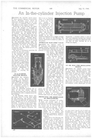
PATENT No. 017,434, which. comes from General Motors. Coyporation, Detroit, Michigan, U.S.A., shows an improved. injection pump of the unit type that is combined with its. nozzle and ,fitted to each engine cylinder... ' .Referring to the drawing, the upper end of the plunger is arrangedto receive an operatingtappet,. whilst the—, bottom of the body terminates in the spray noiile (I). : The.Puinjo" drierates as follows: On the, descent ofplunger it 'fir"st Obstructs the inlet 'port (2) which is kept supplied with fuel under light' Pressure. Further . downward Mov,ernent then returns fuel to the drain .port .(3) until this, too, is closed by the "descending helical edge (4). Thereafter, the pressure rises, forces the check:-Valve (5) from its seating and fuel flows to the nozzle. Injection terminates when the release groove (6)
reathes"the 'ports. • • -.." So much is well-known practice; the novelty in this case.is_that at the lowermost Position of the plunger the inlet port, the release groove and the drain port are all in line, a position in which the supply pressure of the fuel can give a Momentary straight-through flow which carries away any vapour that may be present in the regi o T1. Regulation is obtained in the„ usual manner by rotating the plunger.
• DUAL-PURPOSE TRACTOR BRAKES
PATENT No. 619,874, comes from Harry Ferguson, Ltd., Fletcham
stead Highway, Coventry, and deals with the brakes of agricultural tractors. It is common practice to assist the steering Of a
tractor by selectively braking one or other of the rear wheels, and the patent shows how this can be aChieved, in conjunction with a-coupled action for full braking.
In the drawing, which shows only the brake lever, 1 is the main pedal for full operation; this rotates a shaft (2) which, via pull-rods (3) operates the brake spindles (4) in an anti-clockwise direction. To brake on one wheel only, one of the pedals (5) is depressed. This might be supposed to rotate the brake spindle in the opposite direction, but this is not so, because when it is depressed, it, pivots, not on its. . own. spindle,. but about pivot-pin_ 6. .11 is compelled . _to do . this because the pullrods arc. locked in . . tension, by an upper_.: stop (7) to themain pedal: The action is to rotate the brake" spindle in an anti-" " "
clockwise direction by a toggle arrangement, not shown in ,this' drawing, but clearly' ilInStrated in detail in others in the palent.
HYDRAULIC RAM -LIMIT. VALVE.
PATENT No. 620,213, refers 'to hydraulic rain cylinders as used in tipping vehicles, and deals with a valve for automatically relieving the working pressure so soon as the ram reaches its
full travel. The patentee is E. Bentley, 986, Chorley Old Road, Bolton, Lancs.
The drawing shows a section of a two-stage telescopic ram. The release valve (I) is attached to a rod (2) fitted with a head. (3). The head is engaged by the left-hand end of tube 4 when the ram is fully extended, and .the tube itself is moved when a flange (5) on the inner cylinder makes contact with a projection (6) on the tube, so that a double-length movement is allowed for. When the valve is opened it by-passes the flOid and so terminates the lift. It can also be worked by a 13owden wire on the outside for controlling the descent of the ram. The pump and the release valve are both housed in the ram end, so that no external piping is necessary. The pump is driven by a universally jointed shaft from the vehicle engine.
PROTECTING THE RESISTANCES OF TROLLEY BUSFS
THE starting resistances of trolley. buses are usually open to the atmosphere for purposes of cooling, but the practice has the disadvantage that dirt, stones and, in sea air, salt can reach them and cause damage, To prevent this is the object of a design shown in patent No. 620,627 by J. Dabbs, and Sunbeam Commercial Vehicles, Ltd., Moorfield Works, Wolverhampton.
Referring to the drawing, the resistances are contained in a box (1) which is fed with a draught of air by the forward motion of the vehicle. The air enters through a grille ('2) af the front and is discharged from the open rear end. The resistance banks (3) are laid diagonally, a position which is said to give such adequate conling that smaller resistances can safely be employed without' fear, of • their heating up to a dangerous degree.
AN OIL SEAL FOR OSCILLATING SHAFTS
DA-TENT No. 620,927 comes : from G. Roberts and Guy Motors, ,Ltd., Fallings Park,Wolverhampton, and deals with oil seals for shafts, particularly those .which have. only a partial rotary motion, as, for example, the brake cam-shafts of a road vehicle. The drawing shows such a shaft with the oil seal applied to it. It consists of three parts, an outer metal ring .(1), an intermediate rubber diaphragm (2) and an Inner metal ring (3), all of which are bonded into a unit. Both the outer and inner members are frictionally fixtd to their surroundings, so that the partial rotary motion is accommodated by the flexing of the rubber; the rubber diaphragm, it will be noticed, is thinned down irk the middle so as to-give increased flexibility. 'By the use 'of this device, a hearing once filled with lubricant should. remain So for ark indefinite period, thus -making for a longer life of such parts with less need for periodical servicing.