


NOVEL DAIMLER VALVE GEAR.
Page 32
If you've noticed an error in this article please click here to report it so we can fix it.
A Résumé of Recently Published Patents.
ONE OF THE most interesting inventions we have seen for some time is described in specification No. 216,599, by F. W. ,Lanchester and the Daimler Co., Ltd. It relates to valve-operating gear. On one end of the camshaft is mounted a disc, in the face of which are milled two rectangular grooves, which are at right angles to one another, the centre lines of the grooves intersecting on the axis of the shaft. Immediately opposite this disc, and carried in a bearing in the wall of the timing-case cover, is another disc, from the face of which project two pins. These pins are Situated on the opposite sides of the centre of the disc, being symmetrically disposed to that centre, and they are long enough to penetrate the grooves ni the disc on the end of the camshaft. )'This second disc, which is referred to by the inventors as a driving element, is not in alignment with the camshaft, but is eccentric to it, to an extent equal to the distance from its centre to either
the projecting pins. It follows from :his that each pin in turn, once per revolution, comes opposite to the centre
the camshaft. On each pin is mounted a slipper block, and the two blocks actually engage the grooves in the disc on the end of the camshaft-. This mechanism, already described, constitutes in itself a two to one gear, being actually' equivalent to a two-tooth gearwheel iengaging with a. four-tooth gearwheel.'
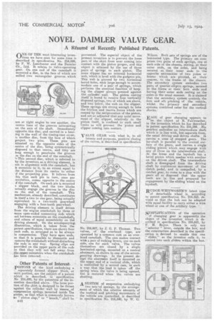
The driving element is itself driven from the engine crankshaft by three or more open-ended connecting rods which act between eccentrics on the crankshaft, and others of equal eccentricity on the driving element. On the accompanying, illustration, which is taken from the patent specification, there are shown four such rods, so arranged as to be always in compression. They have open ends, so that it is possible to dismantle and remove the crankshaft without disturbing the rods in any way. Spring clips are provided on the upper parts of the rods so that they will not fall away_ from the dipper ,eecentrics when the crankshaft has been removed.
Other'Patents of Interest.
PISTONS of the kind embodying a .• separately formed slipper block, or skirt portion, are the subject of a patent which is described, in specification No 216,600, by the patentees of the invention described above. The loose portion of the skirt is designed to be thrust against the cylinder wall by means of compression springs mountea inside The piston, so that what is commonly known
"piston slap," or " knock," shall be B48
prevented. The especial object of the present invention is to prevent the loose part of the skirt from ever coming into contact with the piston proper, and this object is attained by the use of three pairs of springs to each piston. The loose slipper has an internal horizontal web, which is level with the gudgeon pin. This web is pierced by two horizontal bored holes, each large enough to accommodate one of a pair of springs, which performs the essential function of keeping the slipper always pressed against the cylinder wall. The piston casting itself is bored to receive four vertically disposed springs, two of which are above, and twd below, the web on the slipper. These springs are strong enough to take the friction and inertia forces which are caused by the reciprocation of the piston, and are so adjusted that any axial movement of the slipper, relatively to the piston itself, is confined to such small limits as will prevent the piston and slipper coming into contact.
VALVE GEAR with what is, to all intents and purposes, positive closing of the valves, is described in specification
No. 216.607, by J. G. P. Thomas. Two valves, of the overhead type, are operated by a common cam on an over. head camshaft. The cam makes contact with a pair of rocking levers, one on each side, one for each valve. The valves themselves are closed by a single laminated spring, mounted on a central abutment, as shown in one of the accom-. panying drawings. In the present de-sign the abutment itself is mounted on the upper end of a vertical slide, which is controlled by a second cam, in euch a way that the load is taken off the spring when the valve is being opened, but is restored when the valves are shutting.
A SYSTEM of suspension embodying two seta of springs, by the arrange, ment of which the relative amounts of the vertical and pitching movements of the vehicle are controlled, is described in specification No. 216,540, by W. G. Wilson. Both sets o1springs are of the laminated type. The primary set coins prises two pairs of such springs, one at each side of the chassis, resting, at their outer ends, on the axles, and being secured at their inner ends to the opposite ektreraities of two yokes or beams which are pivoted, at their centres, to the frame of the chassis. The secondary system embodies two pairs of quarter-elliptic springs, secured to the frame at their butt ends and having their outer ends resting on the axles in the usual manner. It is claimed that the secondary system controls the fore and aft pitching of the vehicle, whilst the primary and secondary systems combined cater for the vertical shocks.
EASE of gear changing appears to
be the object of E. Fairweather, in the invention which he has described in patent specification No. 216,544. His gearbox embodies an intermediate shaft which is in line with, but separate from, the usual driving and driven shafts. It carries a cone of stepped gears. The lay-shaft is parallel to the conical surface of the gears and carries a single sliding pinion which may engage with any of those on the intermediate shaft. At the lower end the layshaft has a bevel pinion which meshes with another on the driven shaft. The intermediate shaft is disengaged from the driving shaft by continuous movement of the clutch pedal, and is compelled, by a ratchet gear, -to come to a stop with the gears all so disposed that the upper teeth are in line and prepared for engagement by the sliding wheel on the layshaft.
RUDGE-WHITWORTH'S latest type of detachable wheel is, according to patent specification No. 216,553, devised so that the hub can be adapted with equal facility to carry either a wire wheel or one of the artillery type.
SIMPLIFICATION of the operation of changing gear is apparently the object of the invention which is described in specification No. 216,621, by F. H. Royce. There is only one "selector " lever, outside the box, and the construction described in the specification is devised to enable this one slider," as the inventor calls it, to control two such sliders within the box.