


A NEW AND NOVEL ENGINE CONSTRUCTION.
Page 22
If you've noticed an error in this article please click here to report it so we can fix it.
A Resume of Recently Published Patent Specifications.
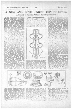
A novel construction of power unit is described in specification No. 127,326, by Henry Yowler and Percy Salmon. The objects of the inventors have been (4 that of relieving the crankpin of much of the shock or 'blow consequent upon the explosion of the combustible , mixture, and this is attained by utilizing the inertia effects of the rapidly travelling piston and rods to counteract the sudden increase of pressirro Which occurs when ignition takes place;(2) to design an engine whereinthe ratio of power to weight is a high one.
The construction embodies a number of cylinder units : we need only consider one of these units. In each, three cylinders are arranged in line vertically. Two arc single acting ; the tilled double acting. As will be surmised, the doubleacting cylinder is the central one, the single acting being the upper and lowest of the three. The effect is to give two power strokes per revolution, the cycle being the Otto. The middle piston is a hollow one, being totally inclosed, • except for the piston rod, which is tubular, and which extends upward to the top piston, and downwasd to the lowest. The upper side of the top piston is open, and serves as a pimp to, coileCt and distribute cooling fluid throughout the piston rod and all three pistons: While it is not so stated in the specification, it would appear, from the fact that there is a clear passage right through this piston to the crankcase, that the cooling medium employed would be most likely lubricating oil. The lowest piston is much deeper than either of the other two, and works in a substantial cylindrical guide, thus acting as a trunk piston or cross-head. It contains the bearings for the gudgeon pin. •
Two sets of valves only are provided. One set is disposed between the top and middle cylinders, and serves to control the gas supply to and exhaust from the top cylinder, which is single acting, and the upper side of the piston of the middle cylinder. The second set of valves is placed between the middle and lowest cylinders, and similarly serves the under side of the middle piston and the lowest cylinder, which is single acting. All the valves are rotary, those which are on the left of the drawing, which we reproduce on this -page from the specification being the MIAS, and those on
the right the outlets. The working components of the cylinder a are separated from one another by piston-rod glands of suitable form; • • C52
Other Patents of Interest.
An interesting radiator design is the subject of No. 127,339, ny A. Lamblin and H. P. Cousin, both Frenchmen. It is pointed out that most radiators as customarily constructed offer considerable resistance to passage through the air at speed, that they are also bulky, and comparatively heavy. In the con et-ruction advocated, a single line of long tubes suitably bent are formed round a central axis, the shape of the complete. nest of tubes being ovoid. At the front, these tubes couple to a single annular header which is designed in eross-section to offer the least air resistance. At the rear end, the tubes enter another header which i.5 conical in form. Suit
able connections are made from the engine to the front header and from the rear }leader back to the engine, again, the useal water pump being placed in circuit 'also. Besides offering, by reason of its shape, a minimum of air resist-sues, it is claimed that the arrangement of the tubes conduces to efficient cooling, inasmuch as, since there is only one row the tubes are therefore subjected to the cooling action of the air dyer their whole surface. Furthermore,. awing to
the shape of the radiator, the tubes are naturally further apart near the front than they are at the rear, thus facilitating the how of air at the front where the writer is hottest. Provision is made in• the design for a Candenser to take care of any steam which may evaporate from the circulating water. This consists of a vertical pipe as long as reasonably pos,sible, coupled to a funnel like chamber provided with a.lid and ball valve. The ball, valve serves to release any harmful pressure which might be generated. The cover is secured by quickly removable hook bolts.
No. 127,339, by G. F. Mort°, is an ingenious method of utilizing the pressure which remains in one cylinder of a multi-Cylinder engine near the end of its explosion stroke, to drive a• super charge of air into another cylinder in which the induction stroke has just been completed.
A form of rotary valve for internal combustion is described in No. 127,361 by W. G. Zeigler, an American. The valve rotatesi within the cylinder between piston and cylinder liner, SO that the piston actually bears on the inside surface of the valve. Suitable ports are cut in this valve, which communicate alternately with exhaust and induction ports in the liner. The valves arc driven by a train of spur gearing, and. as there are two ports in each valve the reduction ratio is four to one, instead of the usual two to one.
The arrangement of gudgeon pin and piston described. in No 127,369 by Alphaero Engines, Ltd., and P. T. Houston is of importance in connection with engines wherein the piston, besides uncovering valve ports by reason of its reciprocating motion, must also revolve slightly about its own axis, to accom
rliah valve operation. The connecting rod, is spherical ended, and. rests in a suitable bearing in the piston.
No. 127,379, by F. B. Killen, describes a construction of pressed-steel wheel, which is particularly suitable for N.A.P. tyres, but which can also be adapted for general use.
No. 127,513, byJ. 11. Churchill, utilizes rolled channels, girders, and T sections for motor vehicle axles by bolting, riveting, or welding the necessary fittings thereto.
No. 127,334, by J. RusdelL is a vehicle in the shape of a barrel, which is propelled by the-power unit travelling inside it an rollers. It appears to be Most suitable for Warfare.