


A Gearless Differential
Page 70
If you've noticed an error in this article please click here to report it so we can fix it.
PATENT No. 824,739 shows a differential gear in which the two output members are coupled by balls used as keys. The balls are free to run in tracks which allow relative movement, (Daimler Benz AG., Stuttgart Unterturkheim, Germany.) The outer casing carrying the crownwheel (1) is provided with numerous semi-circular keyways (2) which contain half of each ball (3). The two output members have undulating semi-circular ball tracks (4), one of which has five sine. waves whilst the other has six. Because of this, a vernier-like action takes place, the balls moving from side to side as this happens.
The design shown is self-locking in the event of wheelspin, having close-fitting conical faces (5) which bind tagether if the bails, by their rapid sideways movement, produce heavy end loads.
LEVELLING VALVE IF the height control unit for an air 1 suspension system gives a too rapid response unnecessary demands can be made on the air supply. A levelling valve with a delay action to obviate this is shown in patent No. 824,397. (The Firestone Tire and Rubber Company, 1200 Firestone Parkway, Akron 17, Ohio, U.S.A.) The control unit is shown in the drawing. It is attached to the frame of the vehicle and the height sensing device is connected to the axle casing. The action is such that a change in frame height results in rotation of a spindle (1). When the spindle turns, a lever fixed to it can open either an inlet valve (2) or an exhaust valve (3).
The valve actuating lever is extended to operate an oil dash-potpiston (4). This mechanism delays the lever movement by a pre-set period to prevent excessive use of air. The delay period can be varied by an adjustable leak through the dash-pot piston_ SWIRL CHAMBER DESIGN
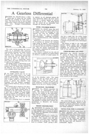
PATENT No. 824,807 states that swirl chambers in the cylinder head of an oil engine should be arranged so that injected fuel wets the chamber walls over as large an area as possible (Maschinenfabrik Augsburg Nurnberg, A.G., 7 Stadtbachstrasse, (13b) Augsburg 2, Germany.)
-Referring to the drawing, the chamber (1) is conical in section, the included angle being 90 degrees. Communicating with the cylinder is a passage in the form of a narrow slot (2) at the swirl chamber end. The slot breaks tangentially into the chamber, explaining the curious outline in the drawing.
The injector is placed on the axis of the cone and in addition to a main central jet directs a number of small sprays (3) on to the chamber walls. The rapid rotation of the air causes these jets to deposit a thin film of fuel over the conical area. This layout is said to give quiet, smokeless running and enables an engine to be run on a variety, of fuels.
ROAD-RAIL TRANSPORT
PATENT No. 822913. describes the carriage of semi-trailers on rail trucks. The frame of: the truck forms rails for the wheels bf 'the semi-trailer, which has, in addition to normal roadwheels, a set of flanged metal wheels. The patent covers the clamping devices for locating the trailer during railtravel_ The patentee is Societe pour l'Union des Ferrovaires et Routiers, 38 Avenue Noche, Paris.
PISTON RESTORATION
I—I A MACHINE for peening the inside
of worn piston skirts to restore them to their original size is shown in patent No. 824,793. (G. Matcharn, 39 Parchment Street, Winchester.) The machine consists of a motor (1), the spindle of which carries a two-lobed cam (2). This imparts two lifts per revolution to a pivoted striker (3) against the pressure of a spring (4). The cam form is a double " snail " giving a slow rise but a rapid fall, the striker being arrested in its descent by an adjustable anvil (5). A link connects' the striker to a hammer (6) provided with a ball-shaped end (7).
The piston is held in the hand and moved about under the vibrating hammer. It is claimed that by skilful handling, the piston can be restored both in size and circularity.
CROSS-BEARER LOCATION
PATENT No. 824,922 describes a means of fixing body cross-bearers so that they are better able to withstand stresses transmitted from the chassis frame. (Barham Bros. (Coach Builders), Ltd., Motspur Drive, Northampton.) The drawing shows both longitudinal and transverse sections of the chassis members (1) and the cross-bearers (2), the two parts being separated by wooden blocks (3). The joint is made by sturdy angle-brackets (4); these are firmly. bolted to the cross-members and held on to the chassis by U-bolts (5). The webs. (6) make the angles very rigid so that twisting forces are converted into extra tension in the U-bolts,
The wood blocks are screwed to the underside of the brackets. Wood is used because it 'prevents electrolytic corrosion between the light-alloy brackets and the steel frame members.
NOVEL FUEL FOR ENGINES
PATENT No. 821,725 comes from the Esso Research and Engineecing Company, Delaware, New Jersey, U.S.A., and describes a scheme for using naphtha as a fuel for oil engines. The naphtha is injected in the usual way and the ingoing air is also lightly carburetted with the same fuel, not, however to a combustible degree.