


Exhaust Blower Increases Power
Page 68
If you've noticed an error in this article please click here to report it so we can fix it.
I T is well known that by fitting a length of exhaust pipe " tuned " to the frequency of the engine speed, an extractor effect will be created by the exhaust gas; this will not only provide a thorough scavenge but can also be made to give a slight supercharge. The use of such an arrangement on a vehicle is impracticable because of the length of pipe required, and the fact that a vehicle engine varies its speed over a wide range. A scheme claimed -to give equal results is shown in patent No. 699,923 which comes from Wade Engineering, Ltd.; Gatwick Airport, -Surrey.
It is proposed to .incorporate in the exhaust system a free-rtinning Roots , type blower. It acts partly as a gas motor and partly as an extractor and is said to give excellent scavenging over a wide range of speeds.
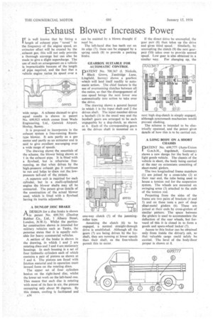
The drawing shows the essentials of
• the scheme, the blowerbeing shown at 1 in the exhaust pipe. It is fitted-with a flywheel, but is otherwise freerunning, so that when driyen by the
• high-pressure exhatist gas it continues to run and helps to draw out the lowpressure tail-end of the_ stream.
.A separate unit is required for each cylinder, but in a .multi-cylindered engine the blower shafts may all be connected. The patent gives details of Ihe construction of the actual blower used, which is fitted with a flywheel having its inertia adjustable.
A DUNLOP DISC BRAKE
A DESIGN for a disc brake is shown
in patent No. 699,701 (Dunlop Rubber Co., Ltd., I Albany Street, London, N.W.1). Whilst the particular construction shown is intended for military vehicles such as Tanks, the patentee states that it is equally _suitable for heavy commercial vehicles.
A section of the brake is shown in the drawing, in which 1 and 2 are rotating discs and 3 and 4 are stationary housings. In each housing is a set of four hydraulic cylinders each of which contains a pair of pistons as shown at 5 and 6. The pistons are faced with friction material and in operation exert inward force on the rotating _discs.
The upper set of four cylinders brakes on the right-hand disc, whilst the lower set work on the loft-hand one. This means that each disc is rotating with most of its face in air, the pistons occupying only about 90 degrees. By this means, cooling is facilitated and
A34
can be assisted by a blown draught if need be.
The left-hand disc has teeth cut on its edge (7); these can be engaged by a spring catch (8) to provide a parking brake.
GEARBOX SUITABLE FOR AUTOMATIC CONTROL
PATENT No. 700,367 (I. Nickels, Black Grove, Tandricige Lane, Lingfield, Surrey) shows a gearbox which will lend itself readily toautomatic action. The chief feature is the use of overrunning clutches between all the ratios, so that the disengagement of one speed brings the next lower one automatically into action to take over the drive.
The drawing shows a general layout in which 1 is the input shaft and 2 the driven shaft. The input member drives a layshaft (3) in the usual way and the layshaft gears are arranged to be each engageable by a dog-clutch, as shown at 4. Each of the corresponding gears on the driven shaft is mounted on a one-way clutch -(5) of the jamming roller type. • Assuming the clutch (6) to be engaged, a normal straight-through drive is established. Although all the gears (7) are being driven by the layshaft, they are running at lower speeds than their shaft, as the free-wheels permit this to occur. If the direct drive be uncoupled, the gear pair (8) then takes up the drive and gives third speed. Similarly, by uncoupling the clutch (9) the next gearpair (10) takes over to provide second speed. Low gear is also obtained in a similar way. For changing up, the next high dog-clutch is simply engaged, although syncromesh mechanism would prevent clashing.
The scheme is intended to he electrically operated, and the patent gives details of how this is to be carried out.
A LONG BODY ON A SHORT CHASSIS
PATENT No. 699,777(Auto-Union G.m.b.H., Ingolstadt, Germany) shows a new design for the body of a light goods vehicle. The chassis of the vehicle is short, the body being carried at the rear on extensions consisting of sheet-metal girders.
The two longitudinal frame members (1) are joined by a cross-tube (2) at their rear end, the tube being used to house a torsion rod for the suspension system. The wheels are mounted on swinging arms (3) attached to the ends of the torsion rod.
Projecting from the sides of the frame are two pairs of brackets (4 and 5) and on these rests a pair of deep sheet-metal girders (6). These are joined at their ends by cross-girders of similar pattern: The space between the girders is used to accommodate the deflection of the rear wheels, but forward of this it -is closed in to form a goods and spare-wheel locker 17).
Access to this locker can be obtained only from inside the driver's cab, so that valuable cargo could safely be carried. 'The level of the body-floor proper is shown at S.