


ANOTHER BRAKE BOOSTER.
Page 32
If you've noticed an error in this article please click here to report it so we can fix it.
A Resume of Recently Published Patent Specifications.
SOME time ago many ingenious devices were produced for the purpose of accelerating the movement of brake shoes while travelling from the position where they are clear of their drums to that point at which they actually contact with the drum, in other words, to boost up the first part of the movement of the shoe, then to introduce a more Powerful leverage than would be possible Were the same ratio of lever to shoe maintained throughout the whole stroke. To describe such mechanisms we gave to them the name "booster."
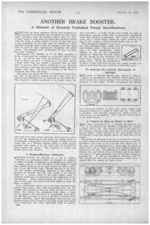
Specification No. 301,943, by F. H. Hall, describes a device of this kind, but working on principle which is new to us. As will be seen from the rawing, where a foot lever is shown, the lever is compos d of two parts, having a hinge where they join, which is brovided with an abutment to prevent their relative movipment in one direction and a spring to keep the two parts together where they butt against each other. The pull rod leading to the shoes is connected just above the hinge. .
The upper view shows the lever as it begins to move under the foot of the driver, turning on the centre (A) as a fulcrum and following the arc indicated by the dotted line. This imparts a rapid movement to the brake shoes, but when they meet their drums and more power becomes necessary for the application of the bralk the helical spring is overpowered, consequently the lever begins tO hinge on the centre (B) as a fulcrum, thereby giving a much greater leverage with which, to do the reat Work of pressing the .Shoes against the drum. • The invention is simple and should prove most effective.
A Brake-efficiency Indicator.
SPECIFICATION No.' 301,774, by A. H. G. Carling,
describes an instrument -which is intended 'to indicate the effect of either acceleration or deceleration by means of a weight, such as a ball travelling freely within a glass tube, which, being set at an angle, causes the ball to gravitate to one end of the tube. Should this■end be the front end and sudden acceleration imparted to the vehicle by opening the throttle, the•'ball will, owing to its inertia, climb to a certain point in the tube, which point, if observed, would wive an, indication of the suddenness of the aceeleration. -4-7iThen testing brakesthe rear end of the tube ia lower than the front, so the bell climbs up when the
brake is applied • . As in commercial vehicles we are far more concerned with testing' brake power than with acceleration tests, we will consider the instrument from the point of view of a brake tester. For testing the suddennesa with which a brake can be applied,' the instrument is undoubtedly well suited, but this does not seem to us to be all that is wanted under present conditiOns, where self-energizing, servo-vacuum and pressure brakes are so much to the front, as all such brakes must necessarily take' some appreciable time to produce
their full effect. A brake of this class would, on such an instrument, compare badly with a defectively constructed brake that jammed on instantly. The former would. he in every way a useful brake, whilst the latter would be one that in wet weather a driver would hardly dare to use.
The instrument appears to. us to be one that indicates shock rather than real braking effect. One of the •f4atures of this specification •which. appeals to us is the remarkable manner in which the inventor makes all the details of his invention perfectly clear, without the 'services of a patent agent. If all the specifications • we have to deal with were as well and clearly written, our task in preparing this page would be considerably easier.
To Prevent the Lateral Movement of Springs. • THE names of Karrier Motors, Ltd., and R. F. Clayton appear in specification No. 299,929, which' relates to a better means for securing springs from moving in a lateral direction in their clips. In this' arrangement the springs
have extensions formed on their sides which engage with projections formed in a cradle in Which they lie. The cradle is provided . with dove-tail engagements which prevent it from moving on its platform. Bolts hold the springs down in the usual manner.
'A Vehicle to Run on Road or Rail.
THE vehicle described by F. A. Pinfold and Drewry Car Co., in specification No. 299,108, is intended for running on either road or rail. The chassis is built in the form of a rail carriage with the usual axles held in horn blocks and flanged wheels. When running on the road, smaller wheels are lowered so that the flanged wheels are held clear of the ground. ; The method of changing from one set of wheels to another is a very, simple One, as long levers fulerumed on or near the rail-wheel axles 6atry at one end the road wheels and, at the other end, are connected, to a screw gear, by means of which either set of wheels can be used without lifting the frame from the rails. No description is given of the means whereby the road wheels are to be driven, nor is any 'reference made as to•what particular class Of work the carriage is intended for. It will be remembered, however, that the War Department has used an arrangement which gives a similar effect for wheels and chain tracks.