


ASSEMBLING A MOTOR COACH WIRELESS SET.
Page 22
If you've noticed an error in this article please click here to report it so we can fix it.
The Selection of Various Components is Dealt With in This Contribution, and the Reasons for Buying Instead of Making are Given.
IN the last article of this series we described in detail how to make a variometer to cover the broadcasting wave-lengths. This design made use of a tubular rotor (as the internal former of a variometer is known) and also a tubular stator, or outside former. Such a variometer, whilst easy to construct and quite efficient in action, will not have a very long range. This is because the distance between the two windings is rather on the large side and cannot be very well reduced in this design of variometer on account of the necessity for allowing sufficient room in which the rotor may rotate.
If a great range is required2 it is essential that we adopt some form of construction which will allow us to reduce the distance between the two sets of windings. The first step in that direction is to make use of a ball-shaped rotor instead of a tubular one. Such a rotor is shown in Fig. 9 The former, on which the wire is wound, is generally turned out of ebonite or wood. If of ebonite, it is very often a moulded fitting, especially in the case of commercial variometers ; if of wood, it must be thoroughly impregnated with paraffin wax as directed for cardboard formers in the last article of this series.
Forming and Securing the Windings.
The winding is divided into two sections and disposed on both sides of the ball-shaped portions of the rotor. In order to facilitate winding and to keep the wire in place, the former is often given a coat of slellac varnish and the .winding proceeded with whilst the shellac is still tacky. A word of warning may well be given here. Never use anything but shellac varnish for sticking the windings of radio inductances in place. Seccotine, glue and other similar adhesives, which are made up with water and are• water soluble, are very poor insulators, even when, apparently, they are quite dry. This is because all gelatinous substances are very largely composed of water and are thus partial conductors ; moreover, they are very hygroscopic—that is, they pick up moisture from the atmosphere—and, thus, their electrical conductivity varies almost daily with the state of the weather. Shellac itself is a very high insulator; it is made up with methylated spirit, which latter evaporates after ithas been applied, and it is quite insoluble in water.
The ball-type variometer rotor has another important advantage over the tubular type. With the latter, the distance between the windings varies as the rotor is rotated, so that the effective inductance is not constant for a constant rotary motion of the rotor. This means that the rate of change of the inductance will be greatest when the two tubes are in. their parallel position and smallest when they are at right angles, so that the setting of the variometer will be more critical in the former position than in the latter.
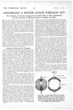
The ball-type variometer rotor, by preserving a more even distance between the windings during the whole of its range, is much better in this respect, although, if used with a simple tubular stator, the improvement is not very great. If, however, instead of supporting the stator winding on a tube, we employ a ball-shaped stator, it will be seen that it is possible to get the two windings still more closely together and to ensure that the distance between them shall remain substantially constant throughout the whole range of the instrument7■If2 moreover, instead of winding the stator on its outside, we contrive to wind it on the iwide of the former, it is possible to get the two windings on stator and rotor extremely close together, with a corresponding
1338 increase in the range of reception of the variometer. This, then, is the form generally taken by the best examples of the modern variometer, and a diagram of an internally wound instrument is given in Fig. 10. The stator generally consists of two ebonite or bakelite mouldings, which are each provided with a circumferential flange in order that they may be secured the one to the other, to barn; when together. a hollow sphere. Bushings are provided, one half in each flange, to accommodate the spindles of the rotor, which latter is also ball-shaped and of such a size as, when wound, will just clear the internal winding of the stator. It will be seen that, with careful design and manufacture, it is possible to reduce the space between the windings to less than one-hundredth of an inch.
The making of such a variometer is beyond the skill of the average wireless amateur and, since the workmanship has to be very precise if the variometer is to be successful in action, it is better bought ; this more especially as even a high-class instrument can be obtained for between 15s. and £1. As a matter of interest it may be stated, however, that the internal winding is generally carried out by winding in the first instance on a :ball former of such a size as to bring the outside of the winding to be an exact fit inside the stator. The winding is done over thin paper. The winding is then thoroughly shellaced and when tacky the ball former with the winding is pressed into the stator half-former. When thoroughly dry the two are separated, the winding and the paper lining remaining inside the stator. The paper is then carefully removed from the winding and the latter given another good coat of shellac and baked. Excellent variorneters are made by the leading radio manufacturers, those that the writer can vouch for from personal experience being manufactured by Mclelland, Fallon, and The General Radio Co., whilst experience is now being obtained with the lgranic R. H. variometer. In subsequent issues we will deal with the method of making some of the component parts and with the selection of others for the construction of the type of four-valve set recommended by The Commercial Motor for the reception of broadcast concerts on a motor coach.