


An Excess Fuel Device
Page 76
If you've noticed an error in this article please click here to report it so we can fix it.
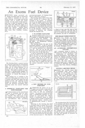
f NJECTION pump governors are I usually provided with an excess-fuel Stop which is intended for use only before starting. If wrongly used during running, fuel is wasted and smoke created. It is the object of the improvement that it shall be possible to apply excess fuel only when the engine is at rest; such are the views expressed in patent No. 764,070. (Simms Motor Units, Ltd., and Z. Miracki, both of. Oak Lane, East Finchley, London, N.2.)
The drawing shows a general section of a governor operating on conventional lines. The full-load stop is a latch (1) which can be swung sideways on its pivot pin (2) to give excess fuel for starting. The latch is moved by pressing down a spring-loaded plunger (3), provided a sliding locking bar (4) is in a position to permit the plunger to descend.
The locking bar is coupled to the rack-rod of the pump via a lever (5) in a manner such that only when the fuel setting is in the " off " position can the plunger be operated. Once the engine starts, the governor movement automatically resets the normal full-load stop.
A SPHERICAL TURNTABLE FOR SEMI-TRAILERS
AN improvement in the conventional type of turntable used for semitrailer coupling is shown in patent No. 764,435. The chief point is that the coupling faces instead of being flat are part-spherical, thus permitting
universal movement. (I. Vaillant, Saint Marcel, Marseilles, France.) The drawing shows half of joint which consists of a concave disc (1) attached to the tractor. A crosswise slot (2) in the middle receives the kingpin, whilst in the mating convex disc the slot runs in a longitudinal direction. These crossed slots Permit the universal movement to occur yet provide a good fit on the king-pin. Safety stops are provided to preserve the coupling should the king-pin fail.
A PLATFORM ELEVATOR
A POWER-OPERATED platform for in. loading or unloading goods is dis
closed in patent No. 763,810. The chief point is the geometry employed in the links. (C. Malmstrom, .Alviken, Fiskeby, Sweden.) The drawing shows the gear in its lowermost position. A pair of parallel 'links (1 and 2) are pivoted on the frame at 3 and are powered by a hydraulic ,ram (4). The ram can lift the load platform from the ground level shown up to the level of the body floor.
It will be noticed that in the position shown the links are not quite parallel; this is because an elbow-type joint (5) is broken open so as to permit the platform to touch the ground. As soon as the lifting force is applied, however, the elbow joint is pulled into line and the motion thereafter becomes truly parallel.
ALTHOUGH the piston of an oil engine can be made to approach the cylinder-head closely, a certain clearance must be left for mechanical reasons. The space so formed can hold quite a considerable quantity of compressed air, and patent No. 764,651 shows a combustion system in which a special stream of fuel is injected into the clearance region: (Lanova A.G., 16 Bahnhofstrasse, Zurich 1, Switzerland.)
Referring to the drawing, , the head is provided with an energy cell (1) into which some of the air is compressed, though the bulk of it is held in the combustion chamber (2). The injector 3 gives two fuel jets, one of which (4) heads for the energy cell while the other (5) is directed downwards into the plane of the clearance space 6. This deposits a cloud of fuel into the base of the combustion chamber, and the fuel is said to be blown into the clearance by the pressure rise due to combustion.
DISC-BRAKE-IMPROVEMENTS PATENT Nos. 765,001 and 765,002 disclose a design for a disc brake. The two chief points are that provision is made for automatic take-up of slack, and a self-energizing action is given by roil-on cams. (Lambert Brake Corp., St. Joseph, Michigan, U.S.A.)
AN AUTOMATIC CENTRIFUGAL CLUTCH .
AN automatic clutch is shown in patent No. 764,416, the action being a combination of centrifugal and hydraulic mechanisms. Gear-pumps run during the slipping periods, and their circuit is restricted and finally blocked
by a centrifugal valve. Free below 700 r.p.m., the drive takes up with increasing speed until a hydraulic lock is formed. (A. Wickman, 10325 Capital Avenue, Oak Park, Detroit, Michigan. U.S.A.).
FITTING L-SECTION RINGS
DATENT No. 763,103 states that
L-sectioned rings have certain advantages in gas sealing, but their shape calls for a special groove in the piston. The patent describes such a ring that can be used in a standard groove. (Hepworth and Grandage, Ltd., St. John's Works, East Bowling, Bradford.) .
The drawing shows the L-section ring (1) in position, and shows also how the spare space in the groove is occupied by a second ring (2). This acts only as a distance piece and though split for assembly, does not make contact with the cylinder wall. The clearance (3) permits the gases to get behind the sealing ring and increase its pressure on the cylinder wall.