


A Daimler-Benz Pre-combustion Chamber
Page 56
If you've noticed an error in this article please click here to report it so we can fix it.
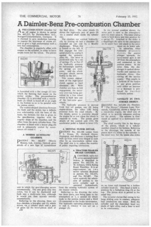
A PRE-COMBUSTION chamber for PA an oil engine is shown in patent No. 663,313, by Daimler-Benz A.G., Stuttgart-Unterttirkheim, Germany. It is claimed to give smokeless running, to require the minimum of excess air, and to give a high performance with a low fuel consumption.
The chamber is angularly offset with respect to the cylinder, in order to leave ample room for the valves. The piston is furnished with a flat trough (1) into which the burning fuel issues on the power stroke. The pre-combustion chamber (2) is provided with a nozzlebush (3) which is faced off at an angle at the bottom so as to lie parallel with the piston crown.
The washer-shaped clearance between the bush and the piston has a definite size relationship with the bore of the bush; the formula for this is given in the specification, together with the angular slope of the chamber, and the offset from the main cylinder-bore. The chamber is fitted with a heater plug (4) and is adequately cooled by waterspaces all round it.
A MORRIS AUTOMATIC GEARBOX
PATENT NO. 662,875 (Morris Motors, Ltd., Cowley, Oxford) gives details of a new type of transmission
unit in which the gear-Changing occurs automatically. The unit gives only two ratios, but it can be duplicated and built into a multi-ratio box, although it would not then operate entirely automatically.
Referring to the drawing, there are Iwo clutches, a low-gear one (I), which drives, via a tubular shaft and a pair of gears (2) the bevel-pinion shaft of A38 the final drive. The other clutch (3) drives the high-ratio pair of gears (4) via a central shaft inside the tubular one.
The clutches are worked hydraulically by forcing oil into a chamber (5) bounded on one side by a flexible diaphragm. When this is forced to the left, it first engages the lowspeed clutch by urging it against the pressureplate (6). The latter is positioned only by a set of springs (7), so that if the hydraulic pressure be increasingly applied, the springs are overcome, and the whole low-gear clutch moves bodily to the left.
This causes engagement of the high-speed clutch against a rigid abutment (8). Both clutches are then in full engagement, the necessary over-run being permitted by a free wheel which is built into one of the low-ratio gear
wheels.
The hydraulic pressure is derived from two oil pumps, one (9) being engine-driven, the other (10) being powered from the road wheels. By this means, power is available should the engine be at rest when the clutch is required to work. The patent gives details of the control unit (11); the accelerator pedal is linked to lever (12).
A MOVING FLOOR DETAIL
PATENT No. 663,106 comes from L. Evans, 25, Orchard Grove, Orpington, and discloses a moving floor built up from metal slats hinged to each other by an intermediate rubber strip. The chief aim is to reduce the number of points requiring lubrication.
A TRACTOR-TRAILER BRAKE CONTROL
• A CONTROL valve for rx servo-operated trailer brakes, is described in patent No. 662,779, by M. Johnson, 134-6, Ealing Road, Wembley. It is an improvement on two earlier schemes disclosed in patents No. 542,453, and No. 567,687. The valve controls the admission of suction to the servo cylinder and is operated hydraulically from the existing hydraulic system of the tractor vehicle.
Referring to the drawing, the valve has three ports, one being open to the atmosphere at 1, a second (2) which leads to the suction source and a thiid (3) connected to the brake servo-motor. The hydraulic operating pressure is led. to end 4. whence it can act • on a plunger (5).
In the normal position shown. the servo port is open to the atmospheric port via inner space 6. The inner sliding valve is held down into this position by a spring (7). Attached to the slider is a diaphragm (8) open to the atmosphere on its upper face and piped to the inner space on its lower side.
In operation, when hydraulic pre ssu re moves the central. plunger upwards, the servo-motor port is cut off from the atmosphere and connected to the suction source. At the same time, the diaphragm is sucked downwardly and opposes the Ihydraulic force, thus cutting off the suction supply. This results in a hold-on of the brakes. in any given position until either an increase or is decrease is produced by further hydraulic action.
NOVELTY IN TWOSTROKE DESIGN.
PDATENT No 663,244 (A. Fletcher, "The Haven," Glaziers Lane, Normandy, Guildford), shows a design for a two-stroke engine, the chief aim of . which is to provide adequate cooling for the piston. The scheme is illustrated as applied to a motorcycle-type engine.
The chief novelty lies in the design of the piston, which is a tubular member closed at the bottom. Referring to the drawings, the outside of the piston skirt (1) slides in the cylinder in the usual way, but the inside also slides
on an inner wall formed by a hollow cylinder head (2). This head is held in position by a bolted-on ring (3) at the top. The piston skirt is ported in the usual way.
The inventor claims that owing to the large. sliding area in contact, adequate heat conduction can occur. Both the cylinder and the dependent head are made of light alloy, and a liner is said to be unnecessary.