


A New Leyland Cylinder Head
Page 60
If you've noticed an error in this article please click here to report it so we can fix it.
A Résumé of Patent Specifications that have Recently been Published
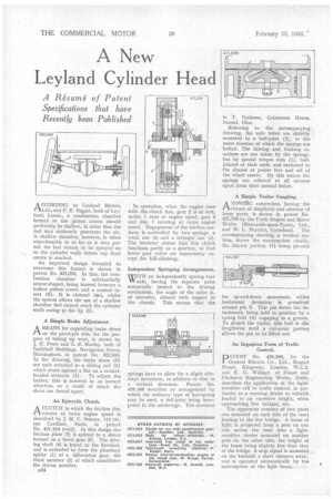
A CCORDING to Leyland Motors, CiLtd., and P. E. Biggar, both of Leyland, Lancs., a combustion chamber formed in the piston crown should preferably. be shallow, in order that the fuel may uniformly penetrate the air. A shallow chamber, however, is often objectionable in so far as it may permit the fuel stream to be sprayed on to the cylinder walls before top dead centre is reached.
An improved design intended to overcome this feature is shown in patent No. 421,836. In this, the combustion chamber is substantially saucer-shaped, being formed between a hollow piston crown and a conical insert (2). It is claimed that, whilst the system allows the use of a shallow chamber fuel cannot reach the cylinder walls owing to the lip (I).
A Simple Brake Adjustment.
AMEANS for expanding brake shoes on the pivot-pin side, for the purpose of taking up wear, is shown by J. H. Pratt and G. E. Manley, both of Guildhall Buildings, Navigation Street, Birmingham, in patent No. 422,04S. In the drawing, the brake shoes (3) are each attached to a sliding rod (2) which abuts against a flat on a conicalheaded setscrew (1). To adjust the brakes, this is screwed in an inward direction, as a result of which the shoes are forced apart.
An Epicyclic Clutch.
ACLUTCH in which the friction disc rotates at twice engine speed is described by J. M. C. Semery, 112 his, rue Cardinet, Paris, in patent No. 421,254 (void). In this design the friction plate (7) is splined to a sleeve formed on a bevel gear (5). The driving shaft (6) is keyed to the flywheel, and is extended to form the planetary spider (1) of a differential gear, the third member (2) of which constitutes the driven member.
J344
In operation, when the engine runs with the clutch free, gear 2 is at rest, spider 1 run 0 at engine speed, gear 5 and disc 7 rotating at twice engine speed. Engagement of the friction surfaces is controlled by two springs, a weak one (4) and a stronger one (3). The inventor claims that this clutch functions partly as a gearbox, so that lower gear ratios are unnecessary except for hill-climbing.
Independent Springing Arrangements.
WITH an independently sprung rear axle, having the separate axles universally jointed to the driving mechanism, the angle of the axles is, of necessity, altered with respect to the chassis. This means that the
is T. Godrnan, Cainscross House, Stroud, Glos.
Referring to the accompanying. drawing, the axle tubes are slidably mounted in a ball-joint (2), to the outer member of which the springs are bolted. The driving and braking reactions are not taken by the springs, but by special torque rods (1), balljointed at their ends, and anchored to the chassis at points fore and •aft of the. wheel centre. By this means the springs are relieved of all stresses apart from their normal duties.
A Simple Trailer Coupling.
ATOWING connection, having the virtues of simplicity and absence of loose parts, is shown in patent No. 421,730 by the Forth Engine and Motor Works (Newcastle-upon-Tyne), Ltd.,
and W. Paynter, Gateshead. The accompanying drawing, a vertical section, shows the construction clearly, the tractor portion (1) being pivoted for up-and-down movement, whilst horizontal deviation is permitted around pin 2. This pin forms the detachment, being held in position by a spring bolt (3) engaging in a groove. To detach the trailer, this bolt is slid lengthwise until a cut-away portion allows the pin to be lifted out.
An Ingenious Form of Traffic Control.
IDATENT No. 420,393, by the 1 General Electric Co., Ltd., Magnet House, Kingsway, London, W.C.2, and E. G. Williner, of Fraser and Chalmers Engineering Works, Eritla, describes the application of the lightsensitive cell to traffic control, in particular as a warning device to vehicles loaded to an excessive height, when approaching low bridges, etc.
The apparatus consists of two posts one mounted on each side of the road leading to the low bridge. A beam of light is projected from a post on one side across the road into a lightsensitive device mounted on another post on the other side, the height of the beam being slightly less than that of the bridge. A stop signal is mounted on the kerbside a short distance away, and is operated automatically by the interruption of the light beam.