


Patents Completed.
Page 28
If you've noticed an error in this article please click here to report it so we can fix it.
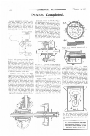
VALVE TRUEING DEVICE.—Lake. —No. 9,024, dated April 29th, 1905.—A support (A) is provided with grooves (Al) (D1) to receive the stem of the valve to be trued, and clamps (B) and (E) serve to hold the valve against lateral displacement, although leaving it free to be
rotated. The upper end of the support projects over the valve, and in it is a screw-threaded adjusting pin (G). At the side of the support is secured a cutter (H), and when the adjusting pin (H) is screwed down upon the valve, the under bide of the valve head is brought against the cotter; by rotating the valve when in this position it will be seen that the head is automatically trued to the stein.
DRIVING AXLE.—Ader.—No. 10,701, dated under convention November 18th, 1904.—The axle is tubular and formed in two parts (1-1, HI) respectively, each of which carries one pinion (G or 01) of the differential gear. Both shafts are rotatably supported at their ends upon a hollow shaft (K), their inner ends run upon a brass L having a central flange which separates them, whilst the outer ends run upon brasses (0) secured to the hollow shaft (K). The ends of the shaft have bolts screwed into them, provided with nuts (V) which keep the wheels and other parts in place, and a ball-bearing (Z) is introduced at each end to reduce friction. DOUBLE-CONE CLUTCH.—Mica.— No. 20,609, dated under convention October 10th, 1904.—A double-coned member (A) is secured to one of the shafts (I). The corresponding clutch member (R) is secured to the shaft (II). Carried on the member (B) by spring-controlled studs (a) is a ring (C) adapted to bear against the opposite side of the member (A) front that occupied by the clutch part (BI. Other studs (e) are carried by the ring (C) and project through the clutch part (B), and cam members (g) are pivoted to the member (B) and adapted to bear against the pins (e). The cants (e) are carried by arms (g) connected to an operating ring (h), When the ring (10 is slid outwards, the ring (C) is forced away from the clutch member (A), and this in turn is brought away from the member (B) by spring-controlled studs (i) carried by a ring (k) fast on the shaft (I). When the ring (hi is released, the clutch automAtically comes into operation.
WHEEL TIRE.—Cantono.—No. 2,454, dated February 2nd, 1905.--A hempen or other rope (21 is wound round the wheel, whose rim is shaped in the form of a spiral to permit lapping of the ends of the rope over the sides of the wheel as shown. One end is permanently fixed, and the other is preferably connected by a spring-controlled chain (4) passing over a pawl and ratchet device (7), so that as the rope stretches, the slack may be automatically taken up. The rope may be LUBRICATOR.—Berry.—No. 16,161, dated August 8th, 1905.—To the end of the journal a pin (c) is secured, carrying a pendent arm (d). A toothed wheel (i) is rigidly secured to the pin (c), and a wheel (hi is pivoted on a spindle (m) car ried by the arm (c1). As the journal rotates the motion of the wheel (1) as it is carried round with the journal is imparted to the wheel (It) by an intermediary pinion (j) free on a stud (k). The wheel (h) carries a roller or wheel (/) which bears against the underside of the journal (b), and is supported by a sleeve g). The lower portion (1) of the journal box (a) is filled with lubricant, and as he wheel (f) rotates it feeds the lubricant against the underside of the journal,