


Worm Contact.*
Page 27
If you've noticed an error in this article please click here to report it so we can fix it.
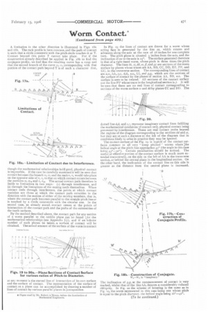
A limitation in the other direction is illustrated in Figs. tea and tfib. The rack profile is here concave, and the path of contact is such that a circle concentric with the pitch circle touches it at T. Contact beyond this point T cannot take place. For if the construction already described be applied in Fig. t81, to find the conjugate profile, we find that the resulting curve has a cusp and that the second branch of the curve w5 wi corresponding with that portion of the contact path beyond T is of such a character that, though the mathematical relationships hold good, physical contact is impossible. If the case be carefully examined it will be seen that contact between the branch w5 tr1 and the rack r1 r5 would take place on the opposite side of 1.1 rA, to that on which contact occurs between the portions ir5 wio and r5 rm. The actual contact path therefore is liable to limitations in two ways : (z) through interference, and (z) through the limitations of the mating teeth themselves. When contact ends through interference, the points at which contact vanishes are those at which the contact path coincides in the direction with the motion of either of the moving members, that is, where the contact path becomes parallel to the straight pitch linear is touched by a circle concentric with the circular one. In the second case, as already stated, contact ceases at the points of intersection of the contact path and the paths of the extremities of the tooth surfaces.
By the method described above, the contact path for any section of a worm parallel to the middle plane can be found (for the mathematical relationships (see Appendix I.) ), and if an infinite number of such planes be taken, a surface of contact will he obtained. The actual amount of the surface of the worm in contact at any moment is the curved line of intersection of its own surface and the surface of contact. The representation of the surface of contact on a plane can be accomplished by drawing a number of lines of contact by various parallel planes in juxtaposition. In Fig. 19 the lines of contact are drawn for a worm whose acting face is generated by the line aa, which rotates and advances along the axis at the rate of 18 inches for one complete turn. The pitch plane is situated 3 inches from the axis, and the inclination of se to the axis is 150.. The surface generated therefore is that of a right-hand worm, whose pitch is three times the pitch diameter. The lines lb. cc, dd, re, if, and gg are sections of the worm surface by planes whose traces are AA, BB, CC, DD, ER, FP. and GO, in the transverse section. The corresponding lines of contact are alai. MI, etc'. dtdi, etch AA, and NI, which are the sections of the surface of contact by the planes of section AA, BB, etc. The surface is seen to be twisted. All sections of the contact surface cut the line PP whose trace in the longitudinal section is p. It will be seen that there are no real lines of contact corresponding to sections of the worm surface cc and dd by planes CC and DD. The dotted line dal and ce, represent imaginary contact lines fulfilling the mathematical conditions of contact only, physical contact being prevented by interference. There are real contact paths beyond the regions of the diagram corresponding to the sections dd and cc, hut they are at such a distance to the left of the diagram that in conditions likely to arise in practice they may be ignored. The contact surface of the Fig. 19 is typical of the contact surfaces common to all very •• steep pitched" worms where :the helical angle at the pitch line approaches 43° (the angle in this case being 43v-5o°). Certain peculiarities should be noticed. The useful or effective portion of the contact surface is much more extended transversely, on the side to the left of AA in the transverse section, or behind the central plane in the longitudinal section. On the other hand, the inclination of the contact line on this side is greater as the distance from the central plane is increased.
The inclination of gigi at the commencement of contact is very marked, whilst that of the line blb, denotes a considerably reduced obliquity. In Fig. 20 the scheme of lettering is the same as in Fig. to, the worm represented in this case being one whose pitch IS equal to the pitch diameter. the helical angle being 16°-420.