


. An Hydraulically Operated Clutch
Page 36
If you've noticed an error in this article please click here to report it so we can fix it.
A Risme of Patent Specifications That Have Recently Been Published
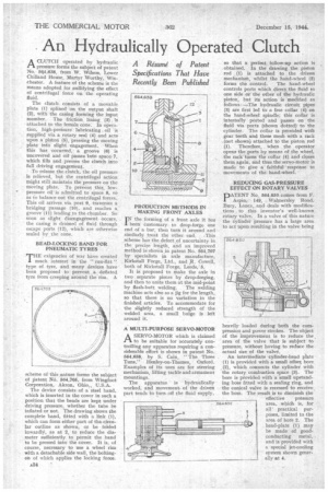
ACLUTCH operated by hydraulic pressure forms the subject of patent No. 5Q4,638, from W. Wilson, Lower ChiBand House, Martyr Worthy, Winchester. A feature of the scheme is the means adopted for nullifying the effect of centrifugal force on the operating if
The clutch consists of a movable plate (1) splined on the output shaft (2), with the casing forming the input member. The friction lining (3) • Is attached to the female cone. In operation, high-pressure lubricating oil is supplied via a rotary seal (4) and acts upon a piston (5), pressing the moving plate into slight engagement. When this has occurred, a groove (6) is uncovered and oil passes Into space, 7, which fills and presses the clutch into full driving engagement.
To release the clutch, the oil pressure is relieved, but the centrifugal action might still maintain the pressure on the moving plate. To prevent ;this, low
"' pressure oil is admitted to space 8, so as to balance out the centrifugal forces. This oil arrives via port 9, traverses a bridging passage (10), and reaches a groove (11) leading to the chamber. So soon as slight disengagement occurs, the casing is drained of fluid through escape ports (12), which are otherwise sealed by the cone.
BEAD-LOCKING BAND FOR PNEUMATIC TYRES HE exigencies of war have created much interest in the " run-flat '! type of tyre, and many devices have been proposed to prevent a deflated tyre from creeping around the rim. A scheme of this nature forms the subject of patent No. 564,705, from Wingfoot Corporation, Akron, Ohio„ U.S.A.
The device consists of a steel band, which is inserted in the cover in such a position that the beads are kept under driving pressure, whether the tube be inflated or not. The drawing shows the complete band, fitted with a link (1), which can form either part of the circular outline as shown, or be folded inwardly, as at 2, to reduce the diameter sufficiently to permit the band to be pressed into the cover. It is, of course, necessary to use a wheel rim. with a detachable side wall, the boltingon of which applies the locking force.
e.34 PRODUCTION METHODS IN MAKING FRONT AXLES I N the forming of a front axle it has been customary to drop-forge one end of a bar, then turn it around and
similarly treat the other. end. This scheme has the defect of uncertainty in the precise length, and an improved method is shown in patent No. 564,707 by specialists in axle manufacture, Kirkstall Forge, Ltd., and R. Cowell, both of Kirkstall Forge, Leeds,. 5.
It is proposed to make the axle in two separate pieces by drop-forging, and then to unite them at the mid-point by flash-butt welding. The welding machine acts also as a jig for the length, so that there is no variation in the finished articles. To accommodate for the slightly reduced strength of the welded area, a small bulge is left around it.
A MULTI-PURPOSE SERVO-MOTOR
ASERVO-MOTOR which is claimed to be suitable for accurately controlling any apparatus requiring a considerable effort is shown in patent No. 564,658, by S. Cain, "The Three Tuns," Henley-on-Thames, Oxford. Examples of its uses are for steering mechanism, lifting tackle and armament mountings.
The apparatus is hydraulically worked, and movement, of the driven part tends to turn off the fluid supply, so that a perfect follow-up action is obtained. In the drawing the piston rod (1) is attached to the driven mechanism, whilst the hand-wheel (2) forms the control. The hand-wheel controls ports which direct the fluid to one side or the other of the hydraulic piston, but its action is modified as follows : —The hydraulic circuit pipes (3) are first led to a free collar (4) on the hand-wheel spindle; this collar is internally ported and passes on the fluid via ports (shown dotted) to the cylinder. The collar is provided with gear teeth and these mesh with a rack (not shown) attached to the piston rod (1). Therefore, when the operator opens the ports by means of the wheel, the rack turns the collar (4) and closes them again, and thus the servo-motor is made to give a faithful response to movements of the hand-wheel.
REDUCING GAS-PRESSURE EFFECT ON ROTARY VALVES
PATENT No. 564,850 comes from F. Aspin, 149, Walmersley Road, Bury, Lanes, and deals with modifications to this inventor's well-known rotary valve._ In a valve of this nature the cylinder pressure has a large area to act upon resulting in the valve being
heavily loaded during both the compression and power strokes. The object of the improvement is to reduce the area of the valve that is subject to pressure, without having to reduce the actual size of the valve. An intermediate cylinder-head plate (1) is provided with a small offset bore (2), which connects the cylinder with the rotary combustion space (3). The bore is provided with a Small upstanding boss fitted with a sealing ring, and thc conical valve is recessed to receive the boss. The result is to diminish the effective pressure
56465E' area, which is, for all' practical purposes, limited to the area of bore 2. The head-plate (1) may be made of goodconducting metal, and is provided with a special jet-cooling system shown generally at 4.