


IGNITION BY CHARGE COMPRESSION.
Page 28
If you've noticed an error in this article please click here to report it so we can fix it.
A Resume of Recently Published Patent Specifications.
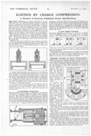
WALTER GERBER, of Berne, Switzerland, in his specification No..232,603, describes a system of ignition which, he sass, solves the problem by providing a means of igniting gas without electricity or a sparking plug. A further claimis that it does not influence the use of wireless apparatus, and is, therefore, of particular value in aeroplanes, etc. The 'invention provides for the compression up to ignition temperature (temperature of combustion) of a small quantity of the charge of the cylinder, the combustion of which causes the ignition of the charge in the main cylinder.
The apparatus consists of a small cylindrical member which may be fixed into the hole provided for the sparking plug. Within this member is a differential piston, which has at its upper end the larger piston and at its lower end the smaller one.
Different bores are provided for Mese pistons, the lower one not communicating directly with the main cylinder, but ohly by means of the small passage shown on the right. On the left will be seen a small passage leading to the space above the larger piston A spring holds the piston up, as shown in the left-hand view, leaving just sufficient space above it for gas from the main cylinder to act above the larger piston, so that near the finish of the compression stroke the spring is overpowered and the gas contained under the smaller piston is compressed to a temperature which causes it to ignite. The ignition of this small quantity of gas causes the smaller piston to rise and allow the ignited gas to escape into the main cylinder and thus to fire the main charge.
It will be understood that owing to the different areas of the two pistons a very considerable degree of compression can be obtained in the lower chamber. This patent is an extr&nely interesting one, and we shall look carefully for developments.
A Centrifugal Carburetter.
FRITZ ASSMUS, of Germany, in specification No. 238,100,
describes a carburetter which, he claims, will divide any fuel into finer particles than by means of the ordinary methods. The result is obtained by the well-known spinning action produced by means of angular planes acted upon by the air in its passage. One of the new features seems to be the fact that two separate air flows are provided, so that the spinning action may be maintained whether the mixture he rieh or not. Another feature whieh is claimed as an advantage is the fact that only one size of carburetter is needed for all size of engines, as chokes can be fitted so that it will work equally well on either small or large engines. This is claimed as a manufacturing advantage, but this advantage is somewhat doubtful, as, with a small and lowpriced car, the carburetter would be as costly as with the largest type made.
A New Bonnet Fastener.
SYDNEY RUSSELL and Edmund G. Russell, in specification No 242,449, show a very useful form of bonnet fastener. The hooked portion is duplicated, one part being fixed to the bonnet whilst the other is spring-mounted and hinged to the frame.
By gripping the two hooked portions together by the hand the lower one is raised, so that it frees itself from its engagement and can then be released, whilst the upper one forms a convenient means of lifting the bonnet.
Hydraulic Clutches for Power Transmission.
CERTAIN improvements are claimed In the specification of
H. J. Meldrum, No. 242,365, in whia a clutch is described of the class in which an eccentric is provided on one member and a number of radially disposed cylinders is arranged on the other member, sl that, when independent movement of the two members is required, fluid contained in the cylinders can circulate freely, but when one member is required to drive the other the movement of the fluid is checked, either partially or wholly, by means of valves.
In passing from the free to the clutched stage there is considerable loss of power by the circulation of the liquid through the passages and valves. The object of the -invention is to provide means whereby this power is utilized. According to the specification, in the liquid circulating system there is pro vided a turbine or reaction wheel, so arranged as to be operated by the circulation of the liquid through the passages of the system. Accarding to the description, the left-hand shaft is the driver, to which is fixed the main body of the clutch, which carries the cylinders and valves, although no key is shown (upper view).
The pistons bear against the ring which surrounds the eccentric and is mounted on numerous rows of balls. The driven shaft is shown on the right hand, upper view, and is provided with conccntriz rows of bills, which steady it lathe main body of the clutch.
Attached to the driven shaft is a turbine wheel (A), upper view. This wheel is widened at its periphery and is provided with three stages of inclined passages, against which the flow of fluid which is discharged from the valves is directed. A sliding disc operates the valves for freeing the clutch. The lower view is a sr ction on the line BB.
452„
242.366
rIALVI• .
=MK
N. SION/LC "41
* Ls.
tievamoto. s
INFT1.
bo. 1,11.4trtemoz.icAvem,se. 104
p/
rr