


Automatic Control in Hobbs Transmission
Page 38
Page 39
If you've noticed an error in this article please click here to report it so we can fix it.
IT has been announced by the Birmingham and Midland Motor Omnibus Co., Ltd., that tests will shortly be made of a Hobbs epieyelic gearbox fitted with automatic control. An example of the gearbox in its manually controlled form, fully described in the August 25, 1950, issue of " The Commercial Motor," was fitted to one of the company's vehicles. After considerable development work by the company and the patentee, Hobbs .Transmission, Ltd., Leamington Spa, the gearbox was employed in a Midland "
Red" bus running on routine services. Its operational characteristics are highly satisfactory and the fuel consumption of the vehicle compares with the average of buses on similar routes. The.amount of maintenance required is small.
Increased Economy
It is confidently expected that the automatic control will materially reduce fuel consumption by providing a gearchanging technique which can be predetermined by the company's engineers.
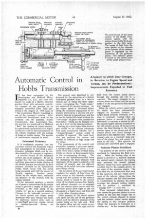
A notable feature of the automatic control unit is its simplicity. It will be recalled that the two traction clutches and three gear-control brake Clutches of the Hobbs gearbox are actuated by fluid pressure, provided by an input-driven pump, which varies with the clutch being energized and with the degree of throttle opening. Another pump, driven by the output shaft, maintains the. pressure on the overrun with the engine -.stopped.
In the automatic gearbox, a second set of gears is incorporated in the output pump to provide a supply of fluid, proportional to the road speed of the vehicle, for use as a control medium.. Changes in the hydraulic pressures of the clutch system and output pump determine when gear changes are made. No additional control units, such as a centrifugal governor, engine cut-out
Or . vacuum-operated device, are required.
B4
The control unit described is one designed for the operation of a Hobbs four-speed gearbox fitted to a Morris Oxford car, in which thethree upper ratios, representing the "high range," are employed for normal running. As the engine speed is increased above idling, the automatic engagement of the traction clutch gives a smooth and progressive take-up in second gear, and the car can be driven fully laden without the "low range" of gears—first, second and third ratios—which can be brought into use by a lever on the steering column.
Starting in a ratio higher than bottom gear would be an obvious advantage with most commercial vehicles, but a "straight-through" system could be provided if required. The hand lever also has positions for reverse and neutral, in addition to high range and low range.
The components of the control unit essentially comprise a governor piston, a spring-loaded selector piston, a kickdown valve and a series of fluid ducts, which are shown in diagrammatic form in the accompanying drawing. The action of the throttle-controlled valve for increasing the fluid 'pressure with depression of the pedal is related to the method of control, and the different settings of the relief valve also influence gear-change timing.
The movement of the governor piston regulates the supply of fluid from the main system to the channels communicating with the cylinder of the selector piston, which is linked to the control valve of the clutch pressure-line. Supply and exhaust channels are so arranged that the selector piston moves with the governor piston from right to left for changing to a higher gear, and from left to right when changing down.
Fluid pressure of the clutch system acts upon the left end of the governor piston and the delivery pressure of the output pump on the right end. With the engine idling and the vehicle at rest, the piston is moved to the right and the fluid from the output pump passes through the metered jet (A) to a reservoir. The supply channels to the selector piston are closed and the spring holds it in the end position with second gear engaged.
When the vehicle gathers speed after the clutch has been automatically engaged by hydraulic pressure, the output-pump pressure increases, and a stage is eventually reached when the governor piston is moved to the left sufficiently to uncover a second jet 03/. The central supply channel is opened by the left annular groove of the governor piston, the fluid flowing to the limited annular space at the spring end of the selector piston and thence through art axial slot to the opposite end. Here the pressure acts on a relatively large section of the piston face and causes it to
move to the left. This operates the contrayalve and third gear is engaged_
Selector Piston Stabilized The position of the selector piston is stabilized by balancing the fluid pressure. When the leading edge of the piston is moved to a position opposite the central supply channel, the trailing edge uncovers the central exhaust channel, which has been opened to the overflow line by the annular groove on the right of the governor piston. The fluid then has an unrestricted flow back to the reservoir, hut any return movement of the selector piston closes the exhaust channel and full fluid pressure is re-established. In practice. the piston overlaps the channel orifices slightly and its position is stabilized by "leakage flow" at each end.
When increased output-pump pressure causes the governor piston to move further to the left, the escape line of the central exhaust channel is closed and the selector piston moves against the spring to the top-gear position, where the pressure is balanced in a similar way. In this instance the piston
is held between the left supply channel and the left exhaust channel.
During the final stage of governorpiston movement, a third jet (C) is uncovered, and this acts as a relief valve to reduce pumping losses when the vehicle is travelling in top gear. The lower gears are automatically re-engaged at predetermined stages as the delivery from the output pump falls with decrease in speed, a qualifying factor being the pressure of the clutch system acting on the opposite end• of the governor piston.
Control Gear Action
Before describing the action of the kick-down valve and the method of engaging the low range, it is appropriate to give more detail of the action of the control gear on the road. Because the pressure of the clutch pressure-line is _raised with throttle opening, the resistance to output-pump pressure is correspondingly increased when the engine is pulling hard. Consequently, changes up and down are then made at relatively higher speeds.
Of greater importance is the difference between change-up and changedown speeds at a given throttle opening.
• This is a function of the drop in pressure when the governor piston uncovers a jet and of the increased r.p.m. of the output pump necessary to compensate the flow through thC jet before the pressure can be further increased. In a typical application, the difference in speed is 7 to 10 m.p.h., when the change is between top and third gear, the change-down being at ,the lower speed. This corresponds to normal driving methods and obviates hunting when the vehicle is driven at a constant
road speed in the change-speed range. A separate regulating device can be incorporated if required.
The kick-down valve is spring loaded and connected to the accelerator pedal by a Bowden cable. It is brought into operation by the final i-in, of pedal movement, against increased pressure, after the throttle has opened fully, and raises the speed at which gear changes are made, both up and down, by reducing the pressure of the output pump by bleeding the line.
Movement of the valve outwards opens an escape orifice to whichfluid from the pressure manifold flows through two channels in the casing and three metered jets in the valve body. One of the channels is not opened until the governor piston reaches the thirdgear position.
In operation, the action of the kickdown valve depends upon the size of the orifice; it could, for example, be used to enable a full-throttle changedown to be made up to a speed of • 35 m.p.h., compared with a normal change-down speed of 15 m.p.h.
No Free-engine Period
Variations in the size of the governor jets, in the clutch pressure settings and in the size of the kick-down-valve jets allow changes to be timed to give maximum acceleration throughout the range. Tests have shown that the best acceleration times cannot be improved upon by a skilled test driver operating the gears manually. Changes up and down are made at any throttle position without a free-engine period, continuous drive being ensured by overlapping-the engagement of the respective clutches. For the low range, reverse and neutral, the selector piston is turned radially by a lever linked to the hand control. The piston is stepped at both ends, and as it is rotated in the normal limiting position to the right, the changed locations leftwards of the effective leading and trailing edges cause the operating shaft to move to the right. In each of these manually controlled positions, the leading and trailing edges remain in the second-gear position between the same supply channel and the exhaust channel.
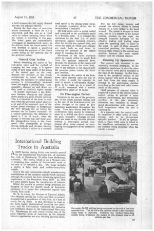
Cleaning Up Appearance
The control unit described is the externally mounted prototype. In the production gearboxes, it takes the place of the control valve and is mounted in the base of the housing. In this form, slots in the peripheral surface of the piston register with ports in the casing, and fluid from the main supply is directed to the appropriate clutches according to the axial and radial movements of the piston.
Fluid pressure of constant value is employed in place of the selector-piston control spring to provide a more uniform performance, and unrestricted overflow of the jets practically eliminates any variation in changespeed characteristics with changes of fluid temperature when the unit is warming up.
As a separate unit, the control could be employed in other types of transmission, such as an air-operated
epicyclic gearbox. In all its applications, a rotary relief valve is linked to the hand-lever mechanism to prevent the clutches being energized when the vehicle is towed.