


Uniform Loading on
Page 56
If you've noticed an error in this article please click here to report it so we can fix it.
Multiple Driving
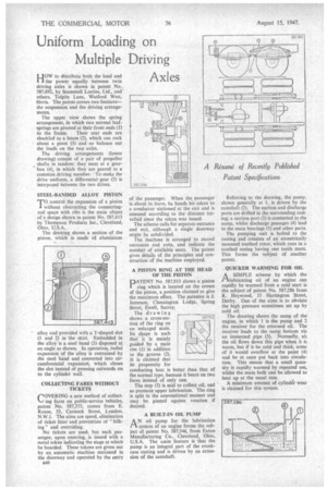
HOW to distribute both the load and the power equally between twin driving axles is shown in patent No. 587,892, by Scammell Lorries, Ltd. and others, Tolpits Lane, Watford 'West, Herts. The patent covers two features— the suspension and the driving arrange
ments.
The upper view shows the spring arrangement, in whith two normal leaf. springs are pivoted at their front ends (1) to the frame. Their rear ends are shackled to a beam (2), which can rock about a pivot (3) and so balance out the loads on the two axles.
The driving arrangements (lower drawing) consist of a pair of propeller shafts in tandem; they meet at a gearbox (4), in which they are geared to a common driving member. To make the drive uniform, a differential-gear (5) is interposed between the two drives.
STEEL-BANDED ALLOY PISTON
TO control the expansion of a piston without obstructing the connectingrod space with ribs is the main object of a design shown in patent No. 587,415 by Thompson Products Inc., Cleveland, Ohio, U.S.A.
The drawing shows a section of the piston, which is made of aluminium alloy and provided with a T-shaped slot (1 and 2) in the skirt. Embedded in the alloy is a steel band (3) disposed at an angle as shown. In operation, radial expansion of the alloy is restrained by the steel band and converted into circumferential expansion, which closes the slot instead of pressing outwards on to the cylinder wall.
COLLECTING FARES WITHOUT TICKETS COVERING a new method of collect ing fares on public-service vehicles, patent No. 587,373, comes from E. Rouse, 53, Cumock Street, London, N.W.1. The aims are speed, elimination of ticket litter and prevention of " bilking" and overriding.
No tickets are used, but each _passenger, upon entering, is issued with a metal token indicating the stage at which he boarded. These tokens are given out by an automatic machine stationed in the doorway and operated by the entry a46 of the passenger. When the passenger is about to leave, he hands his token to a conductor stationed at the exit and is assessed according to the distance travelled since the token was issued.
The scheme calls for separate entrance and exit, although a single doorway might be subdivided.
The machine is arranged to record entrances and exits, and indicate the number of available seats. The patent gives details of the principles and construction of the machine employed.
A PISTON RING AT THE HEAD OF THE PLSTON
PATENT No 587,913 shows -a piston ring which is located on the crown of the piston, a position claimed to give the maximum effect. The patentee is J. Jameson, Chessington Lodge, Spring Street, Ewell, Surrey.
The drawing shows a cross-section of the ring on an enlarged scale, Its shape is such that it is mainly guided by a male rim (1) in addition to the groove (2). it is claimed that its propensity for conducting heat is better than that of the normal type, because it bears on two faces instead of only one.
The step (3) is said to collect oil, and so promote upper lubrication. The ring is split in the conventional manner and may be pinned against rotation if desired.
587913
A BUILT-IN OIL PUMP A N oil pump for the lubrication system of an engine forms the subject of patent No. 587,546, from Eaton Manufacturing Co., Cleveland, Ohio, U.S.A. The main feature is that the pump is an integral part of the crankcase casting and is driven by an extension of the camshaft. Referring to the drawing, the pump, shown generally at 1, is driven by the camshaft (2). The suction and discharge ports are drilled in the surrounding casting; a suction port (3) is connected to the sump, whilst discharge passages (4) lead to the main bearings (5) and other parts.
The pumping unit is b.olted to the casting and consists of an eccentrically mounted toothed rotor, which runs in a toothed casing having one tooth more. This forms the subject of another patent.
QUICKER WARMING FOR OIL
ASIMPLE scheme by which the lubricating oil of an engine can rapidly be warmed from a cold start is the subject of patent No. 587,286 from R. Heywood, 35 Flartington Street, Derby. One of the aims is to obviate the high pressure sometimes set up by cold oil.
The drawing shows the sump of the engine, in which I is the pump and 2 the receiver for the returned oil. The receiver leads to the sump bottom via an immersed pipe (3). Normally, all the oil flows down this pipe when it is warm, but if it be cold and thick, some of it would overflow at the point (4) and be at once put back into circulation. This means that a small quantity is rapidly warmed by repeated use, whilst the main bulk can be allowed to heat up at the usual rate.
A minimum amount of cylinder wear is claimed for this'system.