


A Vehicle-driven Loading Device P ATENT, No. 614,125, shows a loading
Page 26
If you've noticed an error in this article please click here to report it so we can fix it.
device in which the vehicle engine supplies the power. The patentee is H. Kjellberg,
MalniOLimhanin, Sweden.
The drawing illustrates the essential principle, which is that of driving a crane from rollers driven by one wheel of the vehicle, the latter being run on to a low platform in which the rollers are mounted. In the drawing, 1 is the rear wheel of the lorry, resting upon the rollers which drive the hoisting gear (2). A cable passes up the column, the latter being provided with a swivelling head (3) which can swing the raised load either over the ground or over the vehicle. No control gear is mentioned other than a brake; presumably raising and lowering is controlled by the driver from a position in the cab.
A STABILIZED SUSPENSION SYSTEM
QEVERAL patents have lately appeared on the subject of stabilized suspension systems, that is, the coupling of both sides of the vehicle by some
form of pivoted linkage so as to ensure parallel motion. The latest scheme comes in patent No. 613,001, from G. Scanzi and G. Navarini, both of Brescia, Italy. A feature of the system is that torsion springing is employed.
In the drawing, which is stated as being a front view, the wheel axles (not shown) are connected by rods (I) to cross-over rocker arms (2) pivoted on the frame at opposite points. The boss
A36 of each rocker receives the end of a torsion spring (3) which lies longitudinally along the frame. The height of the chassis relative to the ground can be increased by "winding-up" the remote end of each torsion spring, so that the system has the virtue of adjustability.
A NOVELTY IN BODY FRAMES
nECIDED novelty in bodywork is LI disclosed in patent No. 614,004, which describes a body framework built from tube, and covered with panelling, possibly plastic. The patentees are Humber, Ltd., and others, all of Stoke, Coventry.
The drawing shows the framing of a ear body, although the scheme is equally applicable to van and other bodies. The frame is made from steel tubing, presumably welded at all intersecting points, and fitted with screwed studs at the bottom of most of the vertical members. The vehicle frame is drilled to receive these studs, each receiving socket being bushed with rubber to give slight resilience and to prevent squeaks. Eight of the studs are sufficient to form an attachment, and an advantage of the scheme is that.
owing to the ease of detachment, a vehicle can rapidly be converted to one of a different type if alternative bodies be to hand.
NOVEL MEANS FOR OPERATING SLEEVE VALVES
DATENT No. 613,440 refers to a 1 sleeve valve working with a combined rotary and reciprocating motion, and deals with a novel method of imparting the movement. The patentee is Jack Heintz inc.. Bedford, Ohio, U.S.A.
The drawing shows the scheme as applied to a pair of horizontally opposed cylinders, for which it is particularly suitable. Each sleeve (1), at its innermost end, is provided with a ring of gear-teeth (2) which mesh with a pinion (3) carried on a driving shaft (4). Alongside each pinion is a plain disc (5) which rolls in a groove (6) in the sleeve. As the pinion drives the sleeve the disc, owing to the sloping disposition of the teeth and the groove, compels it to oscillate, and thus the combined motion s set up. The effec
tive diameter of the disc and the groov, are equal to that of the pitch circles ol the gears, so that a true rolling motiot without slip can occur.
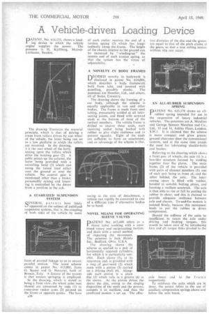
AN ALL-RUBBER SUSPENSION SPRING,
PATENT No, 613,179 shows an allrubber spring intended for use in the suspension of heavy industrial vehicles. The patentees are A. Moulton and George Spencer Moulton and Co., Ltd., 13 and 14, Ashley Place, London, SAVA. It is claimed that the scheme is more compact and gives greater ground clearance than the conventional systems, and at the same time avoids the need for lubricating shackle-bolts and bushes.
Referring to the drawing which shows a front pair of wheels, the axle (1) is a box-like structure formed by welding together four flat plates. The main frame (2) of the vehicle is provided with pairs of channel members (3), one of each pair being in front of, and the other behind, the axle. The intervening '.space is filled with rubber, bonded tti suitable bolting plates, and forming a resilient sandwich. The axle is thus able to rise or fall by putting the rubber in shear, and this is claimed to provide adequate resilience between axle and chassis. To-and-fro motion is resisted firmly, because this movement tends to put the rubber in direct compression.
Should the stiffness of the units be insufficient to retain the axle under driving and braking torques, this would be taken care of by introducing fore and aft torque links pivoted to the axle beam and to the frame respectively.
To reinforce the units which are in shear, the patent refers to the use of auxiliary compression springs above and below the axle beam.