


Commer as Underfloor-engined Six-wheeler
Page 24
If you've noticed an error in this article please click here to report it so we can fix it.
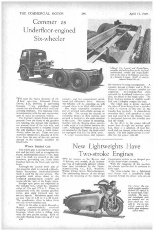
TO meet the heavy demands of oilfield operation, Universal Power Drives, Ltd., Perivale, is converting Commar 7 ton underfloor engined chassis into six-wheeled winch and loadcarrying machines. The imposing front, in conjunction with the neat conversion, goes to make an attractive vehicle.
The Cornincr chassis frame and components from the front to the gearbox are retained, the normal side members are severed short of the rear axle, and an enveloping frame is wrapped round the side members from a point immediately below the cab. These two extra members extend for a distance of 12 ft. 6 ins, from the rear of the cab, and are secured to the original members by fitted bolts.
Winch Behind Cab
The winch gear is carried between the cab and the body, and to strengthen the frame, reinforcement plates 15 ins, deep and in. thick are secured to the side members, preventing the frame from bending between the front axle and the bogie.
Although the Layrub front part of the propeller shaft is retained, a HardySpicer heavy-duty mechanical-jointed shaft is used for the rear section. The propeller shaft drives direct to the overhead constant-mesh transfer and torqw-divicler unit at the bogie centre.
Straight spur gears are employed in the transfer box, which has reduction ratios of 1.26 and 1.73 to 1. These, in conjunction with the normal gearbox ratios, give eight forward and two reverse speeds. Maximum speed with an axle ratio of 6.14 to 1 is 29 m.p.h.' The speedometer drive is taken from the rear of the transfer case.
Drive to the axles is taken through a Rzeppa constant-velocity universal coupling, enclosed in spherical torque housings, which make a sliding joint with the axle pinion casing. Each of the fully floating bogie axles is of 5 -ton A34 capacity, and has conventional spiral bevel and differential drive. Because the vehicles will be operating on soft ground, there is no third differential.
The bogie suspension comprises a pair of inverted semi-elliptic springs on each side. The springs are secured to swivelling blocks at their centres, and pivoted to brackets at the ends attached to the axles. This system of mounting, together with the Rzeppa drive, permits a wide angle of articulation between the axles. Although the 9.00 by 20-in. tyres are retained at the front, the bogie axles are equipped with 8.25 by 20-in. tyres, A 'larger vacuum-servo unit replaces . the standard braking arrangement. A vacuum storage cylinder and a diameter hydraulic master cylinder are employed. Two-leading-shoe units, operated by Lockheed transverse cylinders, arc fitted to the bogie axles. The front braking system is slightly modified, and 13-degree wedges are used.
The winch gear is power operated, the take-off drive being from a sprocket which is secured to the rear of the transfer-box layshaft. A chain-driven two-piece shaft, with sprockets at each end and seeured to the chassis frame, is interposed between the transfer case and the winch.
As the drive to the power take-off passes first through the normal gearbox, There is a selection of four forward and one reverse ratios in the winch speeds. The full engine power is available for the power take-off.