


A Four-wheel-drive Gearbox
Page 58
If you've noticed an error in this article please click here to report it so we can fix it.
PRANSIVIISSION systems for four
wheel-drive vehicles of the "jeep" type are disclosed in patent No. 656,242, by Motor Car Works, National Corporation, Prague, Czecho-Slovakia. The patent points out that when rounding curves the -front wheels of such a vehicle travel further than the rear wheels, and this calls for an 'inter-axle differential gear. To eliminate this costly unit in the case of small vehicles is the object of the scheme shown. .
The patent shows 11 different types of gearbox, all operating on the same basic principle. The drawing shows the simplest type. The input shaft (1) drives a dog-clutch (2) which can be used to select either the low-gear pair of gears (3) or an even-ratio pair (4). The output coupling (5) leads to the rear axle, whilst the front axle is driven from shaft 6.
The essence of the patent is the pro vision of a free-wheel (7) in the frontwheel drive, so that the wheels can overrun if circumstances demand it.
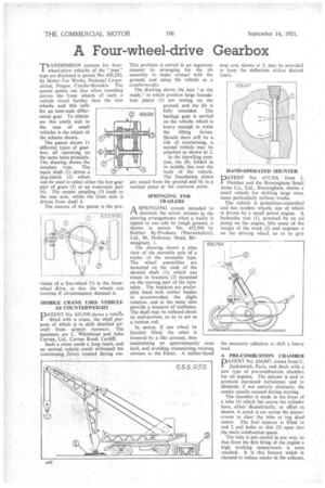
MOBILE CRANE USES. VEHICLE AS COUNTERWEIGHT
PATENT No. 655,950 shows a vehicle fitted with a crane, the chief purpose of which is to shift disabled aircraft from airport runways. The patentees are C. Whitehead and John Curran, Ltd., Curran Road, Cardiff.
Such a crane needs a long reach, and no normal vehicle could withstand the overturning forces created during use. This problem is solved in an ingenious manner by arranging for the jib assembly to make contact with the ground, and using the vehicle as a counlerweight. The drawing shows the Unit "at the ready," in which position large foundation plates' (l) are resting on the ground, and the jib is fully extended. The haulage gear is carried on the vehicle, which is heavy enough to resist the lifting forces. Should there still be a risk of overturning, a second vehicle may be attached as shown at 2.
In the travelling position, the jib, folded in its middle, lies over the body of the vehicle. The foundation plates are raised from the ground and lie in a vertical plane at the rearmost point.
SPRINGING FOR TRAILERS •
A SPRINGING system intended to /-1 diminish the severe stresses in the steering arrangements when a trailer is tipped to one side by rough ground, is shown in patent No. 655,996 by Rubber By-Products (Warwickshire), Ltd., 86, Holloway Head, Bir
mingbam, 1.
The drawing shows a plan view of the steerable axle of a trailer of the turntable type. The wheel assemblies are mounted on the ends of the skewed shaft (1), which can rotate in brackets (2) mounted on the moving part of the turntable. The brackets are preferably lined with rubber bushes to accommodate the slight rotation, and at the same time provide a measure of resilience. The shaft may be reduced about its mid-portion, so as to act as a torsion rod.
In action, if one wheel be forcibly lifted, the other is lowered by a like amount, thus maintaining an approximately even keel, and avoiding transmitting twisting stresses to the frame. A rubber-faced stop arm, shown at 3, may be provided to keep the deflection within desired limits.
HAND-OPERATED SHUNTER
DATENT No. 655,704, from J.
Fletcher and the Birmingham Small Arms Co., Ltd., Birmingham, shows a small vehicle for shifting large ones, more particularly railway trucks.
The vehicle is pedestrian-controlled and has tandem wheels, one of which is driven by a small petrol engine. A hydraulic ram (1), powered by an oil pump on the engine, lifts some of the weight of the truck (2) and imposes it on the driving wheel, so as to give the necessary adhesion to shift a heavy load.
A PRE-COMBUSTION CHAMBER PATENT No. 656,047, comes from C.
Zackiewith,.Paris, and deals with a new type of pre-combustion chamber for oil engines. The scheme is said to promote. increased turbulence and to diminish, if not entirely eliminate, the smoke usually created during starting.
The chamber is made in the form of a tube (1) which lies across the cylinder bore, either diametrically, or offset as shown. A notch is cut across the pistoncrown to clear the tube at to dead centre The fuel injector is fitted to end 2 and holes or slits (3) open into the main combustion space.
The tube is not cooled in any way,' so that from the first firing of the engine a high working temperature is soon reached. It is this feature which is claimed to reduce smoke in the exhaust.