


A Front-wheel-drive Suspension System DATENT No. 734,601, comes from
Page 74
If you've noticed an error in this article please click here to report it so we can fix it.
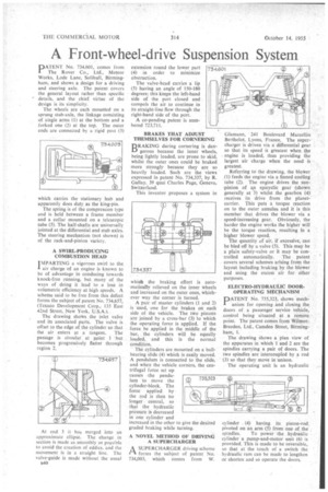
The Rover Co., Ltd., Meteor Works, Lode Lane, Solihull, Birmingham, and shows a design for a driving and steering axle. The patent covers the general layout rather than specific details, and the chief virtue of the design is its simplicity.
The wheels are each mounted on a sprung stub-axle, the linkage consisting of single arms (1) at the bottom and a forked one (2) at the top. The outer ends are connected by a rigid post (3) which carries the stationary hub and apparently does duty as the king-pin.
The spring is of the compression type and is held between a frame member and a collar mounted on a telescopic tube (5). The half-shafts are universally jointed at the differential and stub axles. The steering mechanism (not shown) is of the rack-and-pinion variety, A SWIRL-PRODUCING COMBUSTION HEAD IMPARTING a vigorous swirl to the
I air charge of an engine is known to be of advantage in conducing towards knock-free running, but many of the ways of doing it lead to a loss in volumetric efficiency at high speeds. A scheme said to be free from this defect forms the subject of patent No. 734,657, (Texaco Development Corp., 135 East 42nd Street, New York, U.S.A.).
The drawing shotys the inlet valve and its associated parts. The valve is offset to the edge of the cylinder so that
the air enters at a tangent. The passage is circular at point 1 but becomes progressively flatter through region 2.
At end 3 it has merged into an approximate ellipse. The change in section is made as smoothly as possible to avoid the creation of eddies, and the movement is in a straight line. The valve-guide is made without the usual R40 extension round the lower part (4) in order to minimize obstruction. . The valve-head carries a lip (5) having an angle of 150-180 degrees; this keeps the left-hand side of the port closed and compels the air to continue in its straight-line flow through the right-hand side of the port.
A co-pending patent is numbered 723,711.
BRAKES THAT ADJUST THEMSELVES FOR CORNERING
RAKING during cornering is dangerous because the inner wheels, being lightly loaded, are prone to skid, whilst the outer ones could be braked more stronglybecause they are so heavily loaded. Such are the views expressed in patent No. 734,337, by R. Gallay, 39 quai Charles Page, Geneva, Switzerland.
This inventor proposes a system in which the braking effort is automatically relieved on the inner wheels and increased on the outer ones, whichever way the corner is turned.
A pair of master cylinders (1 and 2) is used, one for the brakes on each side of the vehicle. The two pistons are joined by a cross-bar (3) •to which the operating force is applied. If the force be applied in the middle of the bar, the cylinders will be equally loaded, and this is the normal condition.
The cylinders are mounted on a. ballbearing slide (4) which is easily moved. A pendulum is connected to the slide, and when the vehicle corners, the centrifugal force set up causes the pendulum to Move the cylinder-block. The force applied by the rod is then no longer central, so that the hydraulic pressure is decreased in one cylinder and increased in the other to give the desired graded braking while turning.
A NOVEL METHOD OF DRIVING A SUPERCHARGER
A SUPERCHARGER driving scheme forms the subject of patent No. 734,003, which comes from W.
GIamann, 241 Boulevard Marcellin Berthelot, Lyons, France. The supercharger is driven via a differential gear so that its speed is greatest when the engine is loaded, thus providing the largest air charge when the need is greatest.
Referring to the drawing, the blower
• (1) feeds the engine via a finned cooling tube (2). The engine drives the sunpinion of an epicyclic gear (shown generally at 3) whilst the gearbox (4) receives its drive from the planetcarrier. This puts a torque reaction on to the outer annulus and it is this member that drives the blower via a speed-increasing gear. Obviously, the harder the engine works the higher will be the torque reaction, resulting in a higher blower speed.
The quantity of air, if excessive, canbe bled off by a valve (5). This may he a plain safety-valve or it may be controlled automatically. The patent covers several schemes arising from the layout including braking by the blower and using the excess air for other purposes.
ELECTRO-HYDRAULIC DOOROPERATING MECHANISM PATENT No. 735,323, shows mechanism for opening and closing the doors of a passenger service vehicle, control being situated at a remote point. The patent comes from WilmotBreeden, Ltd., Camden Street, Birmingham, 1.
The• drawing shows a plan view of the apparatus in which 1 and 2 are the spindles carrying a pair of doors. The two spindles are intercoupled by a rod (3) so that they move in unison.
The operating unit is an hydraulic
cylinder (4) having its piston-rod. pivoted on an arm (5) from one of the
spindles. To power the hydraulic cylinder a pump-and-motor unit (6) is provided. This is made to be reversible, so that at the touch of a switch the hydraulic ram can be made to lengthen or shorten and so operate the doors.