


An Injection-pump Delivery Control
Page 62
If you've noticed an error in this article please click here to report it so we can fix it.
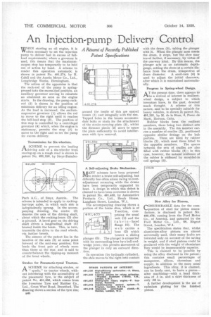
WHEN starting an oil engine, it is W often necessary to set the injection pump to deliver fuel in excess of fullload requirements; where a governor is used, this means that the maximumoutput stop has temporarily to be held out of action by hand. A scheme to render this operation automatic is shown in patent No. 491,274, by R. Cold ll and the Austin Motor Co., Ltd., Longbridge Works, Birmingham.
The action of the apparatus is that the rack-rod of the pump is springpressed into the excess-fuel position, an auxiliary governor serving to reinstate an abutment so soon as the engine starts. In the drawing, the pump rackrod (2) is shown in the position of minimum delivery for an idling engine. As the load is increased, the suctionresponsive governor (1) allows the rod to move to the right until it reaches the full-load stop (3). The position of this stop is controlled by a centrifugal governor (4) which, when the engine is stationary, permits the stop (3) to move to the right and so set the pump for excess delivery.
Transmission for Six-wheelers.
A SCHEME to prevent the leading tlkdriving axle of a six-wheeler from rearing-up on a rough road is shown in patent No. 491,180, by Steyr-Daimler
Puch A.G., of Steyr, Austria. The scheme is intended to apply to rockingbar-type axles, in which each side is independently sprung. In the accompanying drawing, the centre (3) denotes the axis of the driving shaft, about which the rocking-beam (2) also is pivoted. A bevel gear on the driving shaft drives a longitudinal shaft (1) housed inside the beam. This, in turn, transmits the drive to the road wheels, via further bevels.
The essence of the patent lies in the location of the axis (3) at some point forward of the mid-way position; this loads the front pair of wheels more than those at the rear, and is said to counterbalance the tipping-up moment of the front wheels.
Strakes for Pneumatic-tyred Tractors.
A SCHEME for attaching strakes, or " spuds," to tractor wheels, without interfering with the accessibility of the pneumatic tyre, is the subject of patent No. 491,556, which comes from -the lorestone Tyre and Rubber Co., Ltd., Great West Road, Brentford. The drawing shows a section of the tyre rim; B48
around the inside of this are spaced bosses (1) cast integrally with the rim. Tapped holes in the bosses accommodate bolts or studs for the attachment of the strake-carrying plate (3), whilst the distance pieces (2) serve to space the plate sufficiently to avoid interference with tyre removal.
A Self-adjusting Brake Mechanism.
IT ANY schemes have been proposed alto render a brake self-adjusting, but difficulty has often arisen owing to overadjustment occurring while the drums have been temporarily expanded by heat. A design in which this defect is claimed to have been overcome is shown in patent No. 491,455, by Automotive Products Co., Ltd., Brock House, Laugh= Street, London, W. 1.
The accompanying drawing shows a portion of the brake shoe, which is of T-section, cornprising .the usual web (1) and the I abric-'faced flange (4). The web carries a boss (2) which houses a, sliding plunger (5). The plunger is connected with its surrounding boss by a ball-andwedge joint; this permits movement of the plunger in only an outward direction.
In operation (by hydraulic cylinder), the shoe moves to the right into contact with the drum (3), taking the plunger with it. When the plunger nose meets the drum, it stops, but the shoe may travel farther, if necessary, by virtue of the one-way joint. By this means, the plunger acts as an automatic depthgauge, setting the shoes at a certain distance from the drum, irrespective of drum diameter. A snail-cam (6) is used to adjust the initial clearance, after which it is maintained automatically.
Progress in Spring-wheel Design.
AT the present time, there appears to be a revival of interest in resilientwheel design, a subject to which inventors have, in the past, devoted much thought. A scheme of this nature, said to be specially suitable for heavy vehicles, is shown in patent No. 491,181, by M. de la Rosa, 4, Pasco de Marti, Havana, Cuba.
Rubber blocks form the resilient members, there being two distinct sets in the assembly. The rim member carries a number of cradles (2), positioned opposite similar fittings on the hub portion. These are filled by rubber blocks (1), which meet those fitted to the opposite members. The spaces between the sets of cradles are also filled with rubber blocks (4) ; in this case, however, the natural resilience of the rubber is stiffened by moulded-in coil springs (3).
CONSIDERABLE data for the composition of steel for piston manufacture, is disclosed in patent No, 489,478, coming from the Ford Motor Co., of America, and patented by the Ford Motor Co., Ltd., 88, Regent Street, London, W.1,
The specification states that, whilst aluminium-alloy pistons are almost universally used, their many faults are tolerated only on account of the saving in weight, and if steel pistons could be produced with the weight of aluminium they would be immeasurably superior.
This is claimed to he possible by using the alloy disclosed in the patent ; this contains small percentages of manganese, silicon, chromium and copper, in addition to the more usual ingredients. This alloy, it is claimed, can be freely cast, to leave a piston— after machining—with a head thickness of .1 in. and a skirt thickness of only .03 in.
A further development is the use of cadmium plating for the finished piston.