


Reducing
Page 76
If you've noticed an error in this article please click here to report it so we can fix it.
• GEAR NoISES
A Resume of Some Recently Published Patent Specifications
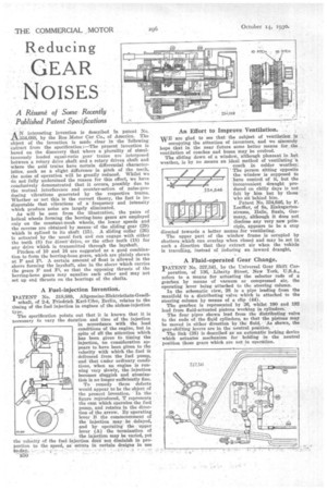
A1%7 interesting invention is described in patent No. 234,668, by the Reo Motor Car Co., of America. The object of the invention is made clear in the 'following extract from the specification :—The present invention is based on the discovery that where a plurality of simultaneously loaded equal-ratio gear trains are interposed between a rotary drive shaft and a rotary driven shaft and where the said trains have certain differential characteristics, such as a slight difference* in pitch of the teeth, the noise of operation will be greatly reduced. Whilst we do not fully understand the reason for this effect, we have conclusively demonstrated that it occurs, possibly due to the mutual interference and counter-action of noise-producing vibrations generated by the respective trains. Whether or not this is the correct theory, the fact is indisputable that vibrations of a frequency and intensity which produce noise are largely eliminated.
As will be seen from the illustration, the pairs of helical wheels forming the herring-bone gears are employed only on the constant-mesh wheels, the lower speeds and the reverse are obtained by .means of the sliding gear (29) which is splined to its shaft (15). A sliding collar (26), is actuated by the usual fork and can engage with either the teeth (8) for direct'drive, or the other teeth (18) for any drive which is transmitted through the layshaft.
Pitches, of 10 and 16 are suggested as a good combination to form the herring-bone gears, which are plainly shown at F and Ft. A certain amount of float is allowed in the sleeve forming the layshaft, also in the sleeve which carries the gears F and Fl, so that the opposing threats of the herring-bone gears may equalize each other and may not set up end thrusts on the bearings of the shafts.
A Fuel-injection Invention.
PATENT No. 318,889, Allgemeine-Elektricitats-Gesellschaft, of 2-4, Friedrich Karl-lifer, Berlin, relates to the timing of the fuel injection in engines of the airless-injection type. The specification points out that it is known that it is necessary to vary the duration and time of the injection in accordance with the load conditions of the engine, but in spite of all the attention which has been given to timing the injection, no consideration appears to have been given to the velocity with which the fuel ik delivered from the fuel pump, and that ender ordinary conditions, when an engine is running very slowly, the injection becomes sluggish and atomization is no longer sufficiently fine.
To remedy these defects would appear to be the object of the present invention. In the figure reproduced, T represents the cam which onerates the fuel pump, and rotates in the direction of the arrow. By operating lever B the commencement of the injection may be delayed, and by operating the upper lever (A) the termination of
the injection may be varied, yet the velocity of the fuel injection cloth not diminish in proportion to the speed, as occurs in certain designs in use An Effort to Improve Ventilation.
WE are glad to see that the subject of ventilation is occupying the attention of inventors, and we s,incerelY hope that in the near future some better means for the ventilation of coaches and buses may be evolved.
The sliding down of a window, although pleasant in hot weather, is by no means an ideal method of ventilating'a coach in colder weather.
• The person sitting opposite thewindow is supposed to have control of it, but the inconvenient draught produced on chilly days is not felt by him but by those who sit behind him.
Patent No. 334,646. by F. Loeffler, of 8a, Zinksgartenstrasse, Halle, Seale, Germany, although it does not disclose any very new principle, appears to be a step directed towards a better means for ventilating.
The upper part of the window frame is occupied by shutters ,which can overlap when closed and may be set in such a direction that they extract air when the vehicle is travelling, instead of inducing an inward draught,
A Fluid-operated Gear Change.
PATENT No. 327,341, by the Universal Gear Shift Cor poration, of 136, Liberty Street, New York, U.S.A., refers to a means for actuating the selector rods of a gearbox by means of vacuum or compressed air, the operating lever being attached to the steering column.
In the schematic view, 28 is a pipe leading from the manifold to a distributing valve which is attached to the steering column by means of a clip (44).
The gearbox is represented by 26, whilst 190 and 192 lead from fluid-actuated pistons working in cylinders.
The four pipes shown lead from the distributing valve to the ends of the fluid cylinders, so that the pistons may be moved in either direction by the fluid.' As shown, the gear-shifting levers are in the neutral position.
The link (38) is described as an automatic locking device which actuates mechanism for holding • in the neutral position those gears which are not in operation.