Tight packed
Page 54

If you've noticed an error in this article please click here to report it so we can fix it.
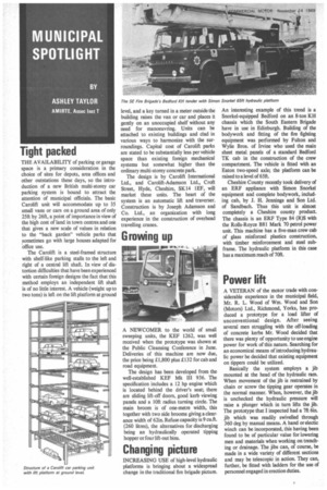
THE AVAILABILITY of parking or garage space is a primary consideration in the choice of sites for depots, area offices and other outstations these days, so the introduction of a new British multi-storey car parking system is bound to attract the attention of municipal officials. The basic Carolift unit will accommodate up to 35 small vans or cars on a ground area of only 2511 by 26ft, a point of importance in view of the high cost of land in town centres and one that gives a new scale of values in relation to the "back garden" vehicle parks that sometimes go with large houses adapted for office use.
The Carolift is a steel-framed structure with shelf-like parking stalls to the left and right of a central lift shaft. In view of distortion difficulties that have been experienced with certain foreign designs the fact that this method employs an independent lift shaft is of no little interest. A vehicle (weight up to two tons) is left on the lift platform at ground level, and a key turned in a meter outside the building raises the van or car and places it gently on an unoccupied shelf without any need for manoeuvring. Units can be attached to existing buildings and clad in various ways to harmonize with the surroundings. Capital cost of Carolift parks are stated to be substantially less per vehicle space than existing foreign mechanical systems but somewhat higher than the ordinary multi-storey concrete park.
The design is by Carolift International Ltd., and Carolift-Adamson Ltd., Croft Street, Hyde, Cheshire, SK14 1EF, will market these units. The heart of the system is an automatic lift and traverser. Construction is by Joseph Adamson and Co. Ltd., an organization with long experience in the construction of overhead travelling cranes.
Growing up
A NEWCOMER to the world or small sweeping units, the KEF 1262, was well received when the prototype was shown at the Public Cleansing Conference in June. Deliveries of this machine are now due, the price being £1,800 plus £132 for cab and road equipment.
The design has been developed from the well-established KEF Mk III 936. The specification includes a 12 hp engine which is located behind the driver's seat; there are sliding lift-off doors, good kerb viewing panels and a 10ft radius turning circle. The main broom is of one-metre width, this together with two side brooms giving a clearance width of 62in. Refuse capacity is 9 cu.ft. (260 litres), the alternatives for discharging being an hydraulically operated tipping hopper or four lift-out bins.
Changing picture
INCREASING USE of high-level hydraulic platforms is bringing about a widespread change in the traditional fire brigade picture. An interesting example of this trend is a Snorkel-equipped Bedford on an 8-ton KH chassis which the South Eastern Brigade have in use in Edinburgh. Building of the bodywork and fitting of the fire fighting equipment was performed by Fulton and Wylie Bros. of Irvine who used the main sheet metal panels of a standard Bedford TK cab in the construction of the crew compartment. The vehicle is fitted with an Eaton two-speed axle; the platform can be raised to a level of 6511.
Cheshire County recently took delivery of an ERF appliance with Simon Snorkel equipment and complete bodywork, including cab, by J. H. Jennings and Son Ltd. of Sandbach. Thus this unit is almost completely a Cheshire county product. The chassis is an ERF Type 84 (R)S with the Rolls-Royce B81 Mark 70 petrol power unit. This machine has a five-man crew cab of glass reinforced plastics construction, with timber reinforcement and steel subframe. The hydraulic platform in this case has a maximum reach of 7011.
Power lift
A VETERAN of the motor trade with considerable experience in the municipal field, Mr. R. L. Wood of Wm. Wood and Son (Motors) Ltd., Richmond, Yorks, has produced a prototype for a load lifter of unconventional design. After seeing several men struggling with the off-loading of concrete kerbs Mr. Wood decided that there was plenty of opportunity to use engine power for work of this nature. Searching for an economical means of introducing hydraulic power he decided that existing equipment on tippers could be utilized.
Basically the system employs a jib mounted at the head of the hydraulic ram. When movement of the jib is restrained by chain or screw the tipping gear operates in the normal manner. When, however, the jib is unchecked the hydraulic pressure will raise a plunger which in turn lifts the jib. The prototype that I inspected had a 711 6in. jib which was readily swivelled through 360 deg by manual means. A hand or electic winch can be incorporated, this having been found to be of particular value for lowering men and materials when working on trenching or drainage. The jibs can, of course, be made in a wide variety of different sections and may be telescopic in action. They can, further, be fitted with ladders for the use of personnel engaged in erection duties.


