


Exhaust Throttle Aids Braking
Page 62
If you've noticed an error in this article please click here to report it so we can fix it.
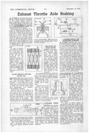
A scHENtE is put forward in patent ri No. 678,476 (Clayton DewartdreCo., Ltd., Titanic Works, Lincoln) to obtain . additional -braking power. by throttling he eadiaust at the same time. as-..the larclinart'.1seakes. are actuated.. . The system iinterided mainly :for vehicles,drivetr by oilengines..
The drawing, shows the:layout of the system; in which the main brakes are wmted by compressed air stored in a reservoir'(1). Upon working the brake pedal "(2); a control valve (3) admits compressed 'air to two cylinders, one of which (4) operates the main brakes, whilst the other (5) pulls the accelerator pedal (6) into the off position. At thesame time, a third cylinder (7) is also energized by the air, and this one closes a throttle-valve , (8) located in. the exhaust Asmost oil engines take in full air irrespective of the load, they act as high-power compressors when the fuel is cut off, and any obstruction of the exhaust would set up a powerful resistance to engine rotation. The exhaust system would have to be suitably strengthened to withstand the possible high pressure. Exhaust brak ing is extensively employed on the Continent.
WATER COOLING FOR THE ENGINE OIL
MODERN high-speed engines tend to overheat the lubricating oil, and in such cases oil-cooling radiators are indicated. A very simple way of providing such a device forms the subject of patent No. 677,664, which comes from Daimler-Benz A.G., Stuttgart, Unterttirkheim, Germany.
Much ik the oil in an engine is at some time thrown onto the walls of the crankcase, and it is therefore proposed to water-jacket the upper half of this unit, and include it in the main cooling circuit of the engine. The drawing shows the construction used, which consists of a sheet-metal pressing
1) fornied to the shape-of the -cylinder block, but spaced a small distanCe thete7 from, so as to create a water-space. • ;
Edge joints fitted With Sealing strips form a water-tight union, all joints being made against machined surfaces A36 on the cylinder-block.. Ribs 2) may he provided to give strength and to direct the flow of water.
MOUNTING OF BOGIE BEAMS CROM Cranes (Dere' ham), Ltd., Dereham, Norfolk, comes patent No. 676,872, which refers to multiwheeled vehicles of the type having rocking beams mounting an axle at each end, each axle carrying two roadwheels. It is vital that the axles shall be able to pivot freely about the beams, and the patent describes a suitable method of con st ruction.
The drawing shows a beam which can rock about a pivot (I). attached to the frame. The beam is a tubular member, and houses a. pair of shafts (2) mounted on self-aligning, roller
bearings located at the 677,664 middle and in housings 3.
Tapered portions (4) carry the axle mount ings, each of which bears a pair of wheels, one on each side of the beam. By mounting the axle carriers on roller bearings, a strong construction is created but there is little friction to resist rocking .pf the axles in response to road variations.
674872 CYLINDER BORES •
FIkeENT No 679,496, comes from W. H. Dorman and CO., Ltd.. Stafford, and shows a method of:. applying chromium to.cylinder bores. They are first bored 0.010 in. oversize, and:then" heavily eleetro-deposited until about 0.005 in. undersize'. The surplus
• is then removed by means of a diamond hone, which, the Patentee claims, leaves a surface well suited for holding lubricant. A RUBBER SPRING FOR SUSPENSION .PURPOSES
ARUBBER assembly that can be substituted for a helical spring as used in suspensions systems, is shown in patent. No_ 679,051, by Morris Motors, Ltd., Cowley, Oxford. When used for its purpose, the device exploits to the full the variable-rate characteristics of rubber and is, moreover, selfstable, requiring no guiding means.
• The spring consists of pairs of dished ' metal pressings (1) assembled back-toback and each pair encloses a rubber ring (2). .Each pair is united by welding at its hub portion (3) and is also joined to its neighbour by the rim, thus forming a one-piece structure that can be handled and used after the manner of a helical spring. The intermediate area (4) can be punched out at intervals to form spokes; these increase the resilience of the metal portions.
COLD WELDING OF ALUMINIUM
CONS1DERABLE progress has been made in the cold welding of aluminium by the sponsors of the process, A. Sowter and
The General Electric, Co., Ltd., Magnet Hous e, Kingsway, London, W.C.2. These inventors now describe in patent No. 676,223, some further details.
It has been found that if commercially pure aluminium be scratch. brushed and then pressed together with force sufficient to reduce its thickness by 70 per cent. a sound weld will be made. The patent deals with the production of metal bellows. .
If a pack of dished washers he assembled in make such .a bellows only alternate pairs must be, welded, otherwise a solid pack. svonlci be produced. The Method used is to scratch-brush only alternate. pairs, so That under pressure they .unite, whilst the non cleaned ones do not. The drawing iliosvs the .Method; the faces between rings _l and 2 are brushed, as are those,between 3 and 4. The Median laces (5) are not, and after indenting as.. shown,, can readily, . be parted. To make parting more certain, the non-joining faces may be lightly smeared with oil.