


TRANSMISSION BY ELECTRICAL MEANS.
Page 17
Page 18

If you've noticed an error in this article please click here to report it so we can fix it.
2.—First Principles of Dynamo and Motor.
FROM THE PRECEDING article, it is clear that, in every system of electrical transmission, there must exist machines capable of forming two functions. One must be able to take the power of the engine and convert it into electrical power and one must be able to take electrical power and convert it back to mechanical power for the _purpose of rotating the driving wheels. Such machmes are called respectively, dynamos and motors, and the 'first principles upon which they work are the following :— L----If an electrical conductor is moved in a magnetic field so as to cut the lines of force in that field, an electrical pressure is set Up along the conductor, and if the circuit is completed a current will flow.
2.--The unlike poles of magnets attract one another and the like poles repel one another.
3.—If a current flows along a conductor, a magnetic field is brought into existence in the neighbourhood of that conductor.
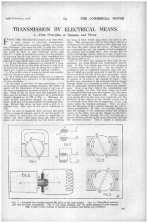
On the basis of the first of these principles, it will be possible to design a simple dynamo, the' action of' which will be illustrative of the action of any one of the more complieated dynamos actually used in practice. , First of all, we must have the magnetic field. This may be brought into existence by a permanent magnet shaped as at PM in Fig. 1. Between the poles of this permanent magnet, we may mount a drum, built up of iron and capable of rotating in bear ings. Round this drum we then wind a coil of insulated wire. One turn of the coil is indicated at AB.
Now we have a magnetic field between the poles of the permanent magnet, and if we use the power of our engine to cause the iron drum or armature to rotate, the wires (AB) lying along the sides of the drum will move alternatively up and down, cutting the lines of force which pass from one pole to the other. The consequence will be that there will be a tendency for an electric current to flow first one way and then the other along the wires. If these wires are connected up and the outside circuit-completed, the current will actually flow. The current will be of the alternating variety, that is to say, it will rise, fall, reverse in direction, rise in the reverse direction, fall again, and so on
Now, if we want the current to flow only in one direction, we must devise our connections accordingly. In Fig. 2 is shown one coil of wire arranged to rotate about the axis (XY). On the spindle is mounted a reel of insulated material, upon the sur • face of which are metal segments (A and B), to which the two ends of the coil of wire are connected. Upon these two metal segments, brushes (C and 1.)), made of carbon or of copper, are caused to bear. The brushes are connected to the external electric circuit through which it is required to send a current. The reel on. which the brushes bear is called the commutator. Now, it is clear that if the commutator and the coil rotate, the time will come when the brush (C) instead of bearing upon the segment (A) will come into contact with the segment (B). If the :current were always flowing the same way round the coil, the direction of the current in the outside circuit would be reversed every time the arrangement of the segments under the brushes changed. Now, we know that the direction of the current through the coil reverses periodically. If then, we arrange things so that the change of the segments under the brushes occurs at the same time as the change in the direction of the current through the coil, we shall get a current flowing ,always in the same direction through the external circuit. This is called a continuous
current. Most of the dynamos with which we are immediately concerned are continuous current machines,
Now, if we refer to the third of the principles mentioned above, we see that we could replace the perinanent magnets in Fig. 1 by electro magnets formed by wrapping a coil of insulated wire round a suitably shaped piece of iron, and then sending the current through the wire. In this way we shall get a magnetic field much stronger than that obtainable from a permanent magnet. Wa might, of course, supply the field magnet coil with current from a separate source as, for example, from a battery, but this is not ereuessary. The iron of the field magnets will always hold a little residual magnetism. Consequently, if we begin to rotate the armature coil some electrical effect will be produced, and, if we connect up the coil so that the current flowing through it will flow also through the field magnet coil, the strength of the inagnetic field will be very quickly increased. The machine is then said to "build up."
Now, there are two possible ways of connecting up the armature coil with the field magnet coil. , In Fig. 3 (a) the armature coil is shown.at A and the field magnet coil at F. Ill and T2 are the terminals at which connections can be made to the external circuit. It will be seen that one end of the armature coil is connected to Ti, and the other end is connected to the field magnet coil through which the connection to T2 is completed. The armature and field magnet coils are then connected up in series, and the dynamo would be called a series-wound machine. It is clear that no current can flow through the field magnet coil until the external circuit is completed.
In Fig. 3 (b) the connections are different. Here both ends of the armature are connected to the ends of the field magnet coil and also to the terminals Ti and T2. When the external circuit is completed, the current from the armature coil has two paths along which to flow; one through the external circuit and the alter, so to speak, along a shunt line through the fielei magnet coil. The dynamo is therefore said to be shunt wound. It will be noticed that with this winding, current can flow from the armature coil round the field magnet coil, while the external circuit is still disconnected, so we have a ready means of increasing the strength of our magnetic field before actually asking the dynamo to do any useful work. It is with shunt-wound machines that we are mainly concerned, but dynamos required to give certain .effects are sometimes provided both with shunt and with series windings. They are then known as compound machines.
The Utilisation of the Current.
This explanation should suffice to indicate sufficiently how a dynamo, driven by a petrol engine, can be got to supply current which can either be stored in a secondary battery or delivered directly to an electric motor. The next point is therefore to consider how the electric motor utilises the current when it gets it. The operation of an electricmotor-is really based on the second of the three principles mentioned above, namely, that unlike poles of magnets, attract one another and like poles repel. The third principle is utilised in conjunction, with this. The electric motor is rhally very similar in appearance and construction to a dynamo ; in fact, many dynamos may be run as motors and vice versa.
Reverting, therefore, to Fig. 1, and regarding this now as an illustration of a simple form of motor, a current is brought from the dynamo, introduced through a commutator, and caused to circulate round the coil AB. This turns the armature into a magnet. No tiern to Fig. 4. Suppose that the direction of the current round All is such that it will turn the armature into a magnet with a north pole at N and a south pole at S. and suppose the field magnet to be so arranged that the south Dole and north pole are as marked. Now, the north pole of the armature will be attracted to the south pole of the field magnet and vice. versa. The armature will, therefore, begin to
e38 rotate in the 'direction indicated by the arrow. It will continue to rotate until its north pole comes opposite the south pole of the field magnet, and its momentum will carry a little further before it steadies down.
We can so connect the coil up to the commutator that just when the north pole of the armature passes the south pole of the field magnet the current through the armature is reversed. We then get the state of affairs shown in Fig. 5. The magnetism of the armature has been reversed owing to the change at the commutator, and the poles are reversed accordingly. We now have the two south poles near together and also the two north poles. These like poles will repel one another, and the result will be that the armature will continue to rotate in the direction of the arrow. The reversal of the current round the armature coil being periodical, this action continues steadily, and the armature goes on rotating always in the same direction.
As in the case of the dynamo, the electric motor may be either shunt or series wound. . As a rule, series winding is preferred for the motor, because it allows the whole of the current to pas § round the field magnet coil, which gives a very strong magnetic field and consequently a powerful torque when starting from a standstill.
The Self-regulating Attribute of the Electric Motor.
Another very interesting point to be noticed is that an electric nibtor is self-regulating. That is to say, it take's only as much/current as is required for the work it has to do. The reason of this is that, as soon as it begins to move, it functions, as a dynamo and
W also as a motor. When its armature rotates in a magnetic field, there is a tendency for a current to be generated in its armature coil as a consequence. This tendency is in a reverse direction to that which urges the current from the dynamo through the coil of the motor. The result is that we have two electrical pressures opposing one another. The more rapidly the armature of the motor rotates the more nearly do these pressures balance one another. The result is that, when the work is light and the armature is therefore able to rotate rapidly, the electrieal pressure or voltage available to send current thYough the coil is very small, and the current urged through is therefore trifling. On the other hand, when the work is very heavy and the motor rotates only slowly, the back voltage is small compared. with the voltage of the dynamo current, and a very considerable current passes through the coils.
Thus, we have in the electric motor, working in conjunction with the dynamo, a system which enables us to exert great power in starting aud at low speeds, but to run at high speeds under light conditions with very little expenditure of power. This explanation, of course, does not profess to be a complete treatise on the principles of. electric dynamos and motors. Many of the reactions involved are very complex, and all that the writer has attempted to do is to give a simple idea of the elementary principles, suffieient to show why an electric transmission system works and wherein lies its particular claim for consideration. Before turning to the consideration of examples, we must, of curse, note the fact that in generating current and afterwards using it, some waste must be involved. The'mechanical power of the engine does not all appear ultimately in the shape of mechanical power at the driving wheels. Some of it has been dissipated in friction and some in heating up of the various coils through which currents have been ceased to flow. It is to avoid these heat losses in particular that the designers of some systems try to arrange for a direct mechanical drive under easy running conditions, utilising the powerful torque of an electric motor only when arduous conditions of running render it desirable to do so.