


ANOTHER ANGLE AXLE DESIGNERS
Page 26
Page 27
If you've noticed an error in this article please click here to report it so we can fix it.
THE opinion that modern commercial vehicles zannot be designed to give greater tyre economy is
. expressed by Mr. A. W. Haigh in ' his article entitled "In Defence of Designers," published in your issue dated April 2. I should have felt inclined to agree with him but for the fact that a short time ago I had the opportunity of testing out a new oscillating-bogie unit, which, to my surprise, eliminated what I had always believed to be incurable defects in design definitely affecting tyre wear. .
Spring Rebound and Rapid Tyre Wear Let us consider the important and puzzling problem of spring rebound. This, in my personal view, is ohe of the chief causes of the rapid wear so often experienced in the case of rear tyres. When a vehicle is travelling at a fairly high speed and a rear wheel meets a pothole the wheel drops and, through force of gravity, the load follows, at least partially, the downward trend. As the wheel clialbs out of the pot-hOle the tyre must, after having taken a heavy shock load, raise the vehicle to its normal level. This form of recovery, repeated many times, results in premature fatigue of the tyre casing, whilst the tread wear is considerably accelerated_ by the resulting wheel-spin.
If a tyre hits a raised object then it and the wheel are forced to make an upward movement and, at the same time, the load is lifted, although, asthe result of the-spring suspension, to a smaller extent. During the brief time the tyre is clear of the road, wheel-spin develops, and tread wiping is bound to result when the spinning tyre again makes contact with the • road. The tyre is thus again subjected to a heavy shock load.
As a designer particularly interested in such matters, I had often studied this 'problem with the object of designing a suspension system that would virtually eliminate spring rebound. Then a few months ago I was asked to witness some tests with a trailer which was equipped with the Burgess Suspension Units. To my considerable surprise I quickly discovered that this suspension system had solved the problem of spring rebound which had puzzled me for so long.
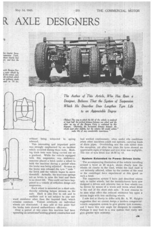
The Burgess Units _comprise four wheels in line. Each pair of wheels is coupled at the top and bottom by two transverse springs pivoted at their centres to the frame members. Each wheel is free to move vertically, but in so doing it will be seen that the load is raised only about half that occupied by the vettical movement of the wheel. This freedom of movement-enables the wheels to " ride " -all raised objects or pot-holes without being subjected to spring rebound.
This interesting and important point was strongly emphasized by an incident which occurred during these tests. Braking trials tests were being carried out on a gradient. While the vehicle equipped with this suspension was stationary, someone placed a brick under a wheel to hold the machine during a period. when the brake was being adjusted. So soon as the brake was released.the tyre " rode " the brick and the vehicle began to move downhill. Actually, the tranverse springs act as levers to raise the load and there is no direct lift. This could not have happened to a vehicle of orthodox design and suspension.
Each wheel is mounted on a short axle, thereby reducing torque stresses on the axle. Each is also free to roll and to oscillate and is not subject to any outward resistance other than the imposed load, 'which remains constant. Violent, overloads on individual wheels are eliminated. I may add at this point that the brake tests showed extraordinary efficiency.
Over a period of two years this machine had been operating on aerodrome-landing-ground construction and
had worked continuously, often under vile conditions when other machines could not operate; carrying loads of drain pipes. Overloading was the rule rather than the exception, yet after two years the tyres showed no appreciable-signs of fatigue aud tyre wear was negligible. The size of tyre fitted was 10.50 by 13.
System Extended to Power Driven Units
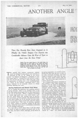
. The accompanying illustration of the vehicle travelling around a bend at 45 m.p.h. shows dearly how the wheels sit closely to the road, whilst the load itself is not seriously affected, either by the camber of the road or the centrifugal force experienced at this speed on such a bend.
The suspension system. I have just described relates only to trailer wheels, but the manufacturers have now designed a driven unit whereby two or four wheels can be driven by means of a worm and worm wheel fitted to the end of the short stub axle. It now remains to be seen what effect the reduced resistance has upon a driven bogie with free oscillating wheels.
I now feel at liberty to differ with Mr. A. VV.
suggestion that we cannot design a modern compiercialvehicle suspension system to give greater tyre economy, and I leave this new angle for designers to consider. Perhaps it may lead to a new system that really will give greater tyre economy.