


Tappets that Adjust Themselves
Page 41
If you've noticed an error in this article please click here to report it so we can fix it.
REGARDED frorn the point of view of the commercial-vehicle user, developments in car design fall into two main classes—those which concern fashion or luxury, and those which are of practical value in improving performance or reducing maintenance. The former are of no interest in the commercial-vehicle field, but the latter always merit attention.
Coming into the latter class is the Zero-Lash self adjusting hydraulic tappet, which has already been standardized on three post-war cars, and is equally applicable to commercial-vehicle engines of either the petrol or oil-fuel type.
Maintenance Reduced
On first consideration, the useful reduction in maintenance brought about by the self-adjusting properties of these tappets would appear to be their chief merit. In practice, this valuable characteristic is only one advantage of the system, and not the most important one at that.
The further benefits result from the fact that the tappets adjust themselves, not to any predetermined clearance, as one might at first imagine, but to a state of no clearance—or zero-lash, to use the American expression.
In consequence, noise from valve operation is reduced to a minimum, but more important are the functional advantages which are brought as a result of the elimination of the normal clearance between the tappet and the end of the valve stem or push-rod. To appreciate this aspect of the system, it is necessary to consider cam design.
Silence Ramps
To a greater or lesser extent, most cams are designed with what is sometimes known as a silence ramp, this term denoting a gradual rise from the base circle of the cam to the point where the contour begins to rise sharply to lift the valve from its closed to its fully open position within a reasonably quick period. This ramp must, of necessity, be planned with a specific clearance in mind, because its purpose is solely to take up that clearance gradually; once -this has been achieved, further rotation of the cam must produce a rapid lift, or the valve will remain in a slightly open position for an undesirably long period.
The plan is reasonably satisfactory so long as the specified clearance be maintained, but any error in clearance will ,obviously result in a variation also in valve-timing. Just how great this variation may be will be appreciated when it is -borne in mind that the silence ramp thay represent as much as 30 degrees of crankshaft movement. If the clearance be less than the amount specified. the ,valve will open -early and close late.
Not only will such errors affect -the breathing of the engine, but, in the case of the exhaust valve, early opening is particularly undesirable, because the valve face will be held slightly off its seating for an appreciable period while the tappet is still on the silence ramp.
Obviously, these troubles cannot occur in a system in which no clearance is provided and in which the designer has schemed his cam contours accordingly. The designer is, in fact, free to concentrate on the ideal timing for the engine characteristics he has in view without being hampered by considerations of achieving a reasonable-degree of silence, and of the possible effects of neglect. As tappet accessibility ceases to be an important factor the designer has a freer hand in laying out engine auxiliaries.
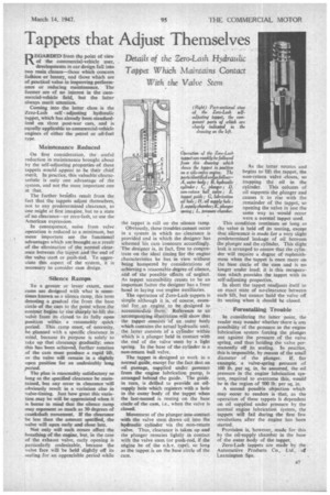
The operation of Zero-Lash tappets is simple although it is, of course, essential for an engine to be designed to accommodate them. Reference to ati accompanying illustration will show that the tappet .consists of an outer body which contains the actual hydraulic unit; the latter consists of a cylinder within which is a plunger held in contact with the end of the valve stem by a light spring. In the base of the cylinder is a non-return ball valve.
The tappet is designed to work in a normal guide. except for the fact that an oil passage, supplied under pressure from the engine lubrication pump, is arranged behind the guide. The guide. in turn, is drilled to provide an oilsupply hole which registers with a hole in the outer body of the tappet when the last-named is resting on the base circle of the earn, i.e., when the valve is cloaca.
Movement of the plunger into contact with the valve stem draws oil into the hydraulic cylinder via the non-return valve. Thus, clearance is taken up and the plunger remains lightly in contact with the valve stem (or push-rod, if the engine be of the o.h.v, type), so long as the tappet is on the base circle of the cam. As the latter rotates and begins to lift the tappet, the non-return valve closes, so trapping the oil in the cylinder. This column of oil supports the _plunger and causes it to rise with the remainder of the tappet, so opening the valve in just the same way as would occur were a -normal tappet used.
This condition continues so long as the valve is held off its seating, except that allowance is made for a very slight predetermined leakage of oil between the plunger and the cylinder. This slight leak is arranged to ensure that the cylinder will require a degree of replenishment when the tappet is once more on the base circle of the cam and is no longer under load; it is this recuperadon which provides the tappet with its self-adjusting properties.
In short the tappet readjusts itself to an exact state of no-clearance between each lift, but cannot hold the valve off its seating when it should be closed.
Forestalling Trouble
In considering the latter point, the reader may wonder whether there is any possibility of the pressure in the engine lubrication system forcing the plunges out against the pressure of the valve spring, and thus holding the valve permanently off its seating. In practice, this is impossible, by reason of the small diameter of the plunger. If. for example, a valve-spring pressure of 100 lb. per sq. in. be assumed, the oil pressure in the engine lubrication system, required to overcome this, would be in the region of 500 lb. per sq. in.
A second possible objection which may occur to readers is that, as the operation of these tappets is dependent on oil supplied under pressure by the normal engine lubrication system, the tappets win fail during the first few revolutions after the engine has been started.
Provision is, however, made for this by the oil-supply chamber in the base of the outer body of the tappet.
Zero-Lash tappets are made by the Automotive Products Co., Ltd., of Leamington Spa.