


TRANSFERABLE BODYWORK.
Page 28
If you've noticed an error in this article please click here to report it so we can fix it.
A Résumé of Recently Published Patents.
• Quite a large number of patents has been taken out in connection with the design and construction of lorries and trailers, with the .object of rendering them easily capable of accommodating removable bodywork, mounted on wheels, and adapted for transference from trailer to lorry, or vice versa, or from lorry or trailer to and from a loading platform. The majority-of these inventions has been described by us in this page as being of 'direct interest to a largo body of our readers. Such a contrivance IS the subject of patent spetification No. 174,537, which appears under the name of J. I. Thornycroft and Co., Ltd.
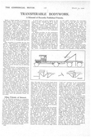
The invention is notable for its simplicity. The principle is exemplified in the one application of it which is depicted in our principal illustration. A lever is fulcrummed on one of the two vehicles, either lorry or trailer. The short arm of the lever is applied to the other vehicle, either as a slot, or as a hook, engaging with a suitable pin. Manipulation of the long arm of the lever serves to bring the two platforms to the same level, when the transportable body may readily be run from one to the other. The object of the invention is to bring these platforms into this position with regard to one another, and the use of a lever in this fashion exemplifies the most obvious way of effecting that object.
There are shown--and deseribeddn detail—several ways of applying the principle, using materials less bulky and more convenient than that to which reference is made above. In one, two resilient brackets are mounted, one to the rear of the lorry and the other at the front of the trailer. (See acccompanying illustrations.) To these brackets are eectered others which present, to the • other vehicle, a pair of hooks, one of which is inverted, while each of a pair is located immediately above or below its fellow, the inside of one hook being towards the inside of the other. A suitable bar is inserted between the upper hook on one vehicle and the lower hook on the other, and the various parts are so located that, as the vehicles approach one anotheit, the bar lifts one and lowers the other until the platform levels are the same.
Other Patents of Interest.
J. S. Marriott proposes to economize the fuel used in an internal-combustion engine by adding to it a small quantity —from one-tenth to one-fifth of an ounce to the gallon of fuel—of a. mixture of alkanet root, block camphor, and petrol. The mixture is prepared by steeping alkanet, root in petrol for from 10 to 12 hours. The camphor is then dissolved in the petrolealkanet mixture, and the resulting fluid carefully strained. The strained liquid is kept in'tightly stoppered containers, and is added to the ordinary fuel as and when required. Suitable proportions of the ingredients used are :—Alkanet root {dried), lb.; petrol (benzole, or other suitable spirit having a specific gravity of from .715 to .725), 1 gallon, block camphor 4 lb. The patent specification is numbered 174,463.
B24 A novel type of rotary engine is the subject of No. 174,434, by F. J. Smith and another. A cam-shaped rotor, which is designed to rotate within a cylindrical watercooled chamber, is fitted with internal oscillating cylindrical valves, which alternately trap the Mixture and deliver it to the combustion chamber.
C. Binks provides, in the carburetter which he describes in patent specification No. 174,493, an easily controlled pilot jet which can be set to give full opening to the jet orifice for starting purposes, and can subsequently be closed until the fuel which passes is sufficient to supply, in conjunction with the main jet, a peeper proportion of fuel to ensure an econonfleally working engine. If necessary, the pilot jet may be closed altogether. As illustrated in the draw'lug which accompanies the specifica lion, the pilot jet is of the kind which opens into the mixing chamber close Ito the edge of the butterfly-type throttle valve. It draws its fuel through a vertical tube, the lower end of which is submerged in the petrol. Communication between this tube and the passage leading into the mixing chamber is by means of a plug valve on the exterior of which is cut a circumferential tapering groove. At its junction with the opening in the plug the eross-seotioral area of this groove is equivalent to that of the full jet opening. The groove tapers away from this point until it vanishes, so that rotation of the plug presents a decreasing passage for fuel, until the vanishing point of the groove is reached, when the supply is cut off.
The safety controlling gear for eleetnically propelled vehicles which is the subject of patent specification No, 174,512, by R. Garrett and Sons, Ltd., is really an improvement on a control gear tented by the same inventor under '6. 164,437. In the previous construction the controller was operated by a pedal or hand lever, so arranged that the current was cut ,off whenever either or .both brakes were applied. It has been found that there were serious -defects in the, former construction. For example, should the driver's foot be kept down
I\fOrCh 54,
on 'the pedal operating the controller, this could not cut off even when the brakes were applied; also, it was not possible to drop from the "full on" position to an intermediate speed.. In the previous patent, too, directly a brake is applied, however little, the contrailer returns immediately to the "off" position, and this may be inconvenient in traffic. Another point was that reversing was effected by a separate switch, eo that there was nothing to prevent the driver from reversing while the vehicle was still in motion and travelling in a forward direction. It is claimed that in the controlling gear which is described in the present specification all these defects have been eliminated.
Means are provided, consisting of suitably arranged cams and pawls, mounted on and around the control spindle, whereby it is possible to drop front the "full on" position to an intermediate position, and this will automatically occur as the effect of a preliminary or alight application of one or other of the brakes, the absolute cutting off of the current being only effected as the result of full actuation of either or both of the brakes. It is also made impossible for the reverse switch to be operated until after the application of the brakes.
An ingenious attempt to improve the regular sparking qualities of a magneto for a V-type engine is described in specification No. 174,524, by H. Lucas and another. The armature is made with its two faces of brass and iron, the pieces of brass being so inserted that they form the two diagonally opposite ends of the armature faces. An armature so made is used in conjunction with stepped polepieces. This construction causes the flux changes which occur in the cone of the &mature at the two sparking positiol* to be greater and more nearly equal than has hitherto been possible.
The same patentee describes, in No. 174,525, a method of mounting the bulbholder of a lamp in a flexible rubber disc, the outer rim only of which is secured to the body of the lamp. It is hoped, by mounting the bulb on a flexible disc of this nature, to protect it from the effects of road vibrations.