


J. & E. Hall, Ltd.
Page 23
If you've noticed an error in this article please click here to report it so we can fix it.
Exhibit :—One 30-35h.p. " Hanford" Chassis; one Saurer Chassis; "Hanford" Gear-box.
This company manufactures the Saurer chassis under license, but, although the vehicles constructed at Dartford follow the general design of M. Adolphe Saurer many of the details have been altered, and certain parts strengthened to conform with British practice and ideas concerning publicservice vehicles. The modified vehicle is known as the Hallford chassis.
The engine is a 3o-35h.p. one, and the cylinders are tionant. in bore, and the piston-stroke is momrn. The two camshafts are hollow, and each has a rod passing through it, from one end to the other. The first of these rods connects the governor with a throttle valve in the induction pipe ; the second is part of an ingenious form of airbrake, whereby a compression stroke is obtained per revolution, in each cylinder, instead of the ordinary Otto cycle. The above is Saurer's patent, and is fitted in addition to the usual foot and hand brakes. The device, which is clever, but somewhat difficult clearly to convey, is contained in the exhaust camshaft. The exhaust timing-wheel is driven in the usual way from the crankshaft, and is part of the two-to-one gear. Instead, however, of being mounted directly upon the shaft, the central hole in the boss of the wheel has two spiral grooves cut in it, which are, in reality, part of a screw having a pitch of 9.25 inches. Sliding within .the boss of the wheel is a gunmetal sleeve, and this has two threads on its outer surface which correspond to the grooves in the boss, whilst the inner surface of the sleeve is provided with four longitudinal slots. The camshaft has four feathers machined upon it, and these fall within the longitudinal slots in the sleeve. The operatingrod, which passes down the hollow camshaft, is attached to the forward end of the sleeve, and a ball bearing is interposed between the connections' to eliminate friction. The camshaft has a central collar, which has a groove round its circumference. A jaw, which is bolted to the crankchamber, fits the groove, and this prevents any longitudinal movement of the camshaft. Ball bearings are fitted to both camshafts. The air-brake is brought into action by a lever working in a sector, fitted to the steering wheel. The lever rotates a double-spiral cam, situated at the foot of the steering pillar; this double cam actuates both the rod contained within the exhaust camshaft, and, also, a throttle in the inductionpipe at one and the same time. The operations are By pulling the lever on the steering wheel over to its maximum amount, the throttle is opened, and the rod in the camshaft is pushed forward ; this causes the sleeve in the timingWheel boss to revolve, and, at the same time, to rotate the camshaft in a forward direction through an angle of 96 degrees. This has the effect of changing the ordinary Otto cycle, as described below—(i) Aspiration ; inlet valves open, exhaust valves shut : (2) compression ; all valves shut : (3) aspiration through exhaust valves ; inlet valves shut : (4) compression ; all valves shut. The engine, thus, virtually becomes an air compressor and draws in air at every stroke, this air being, subsequently, compressed. The result is a powerful brake, elastic in action, with the advantage of cooling the engine, and saving the mechanical brakes.
The carburetter is a patented one, and has two jets, which are separate chambers (sec page 49). The jets are of unequal size, the larger one (0.9mm. in diameter) being in action at all speeds of the engine up to 700r.p.m., at which speed the smaller one (o.8mm. in diameter) is, also, brought automatically into use. The chamber of the larger jet is closed by a flap valve, the spindle of which projects through the carburetter casting, and is fitted with a short horizontal lever, from which depends a rod furnished with a piston. The piston hangs in a bath of glycerine. As the speed of the engine increases above 7oor.p.m., the flap valve is sucked open, and, simultaneously, the piston is forced downwards, and the glycerine passes to the top surface through a small hole drilled for the purpose. The glycerine gives a steady action to the flap valves, which would, otherwise, be jerky in its movements.
The space at our disposal prohibits a full description of this chassis, but mention must be made of a few of the constructional details. The main frame is strengthened by a nickel-steel flitch plate io inches deep, which extends along the central portion of side members, and is 6 feet 6:1 inches long.
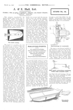
The sliding gears are out from chrome nickel-steel, and all the shafts arc fitted with ball bearings ; this applies, also, to the crankshaft (as illustrated) and differential shaft.
We congratulate this old-established engineering company, whose works are at Dartford, upon its wisdom in taking up the home production of a well-tried Continental design, and upon the improvements they have introduced.