 1
1 2
2 3
3 4
4 5
5 6
6 7
7 8
8 9
9 10
10 11
11 12
12 13
13 14
14 15
15 16
16 17
17 18
18 19
19 20
20 21
21 22
22 23
23 24
24 25
25 26
26 27
27 28
28 29
29 30
30 31
31 32
32 33
33 34
34 35
35 36
36 37
37 38
38 39
39 40
40 41
41 42
42 43
43 44
44 45
45 46
46 47
47 48
48 49
49 50
50 51
51 52
52 53
53 54
54 55
55 56
56 57
57 58
58 59
59 60
60 61
61 62
62 63
63 64
64 65
65 66
66 67
67 68
68 69
69 70
70 71
71 72
72 73
73 74
74 75
75 76
76 77
77 78
78 79
79 80
80 81
81 82
82 83
83 84
84 85
85 86
86 87
87 88
88 89
89 90
90 91
91 92
92 93
93 94
94 95
95 96
96 97
97 98
98 99
99 100
100 101
101 102
102 103
103 104
104 105
105 106
106 107
107 108
108 109
109 110
110 111
111 112
112 113
113 114
114 115
115 116
116 117
117 118
118 119
119 120
120 121
121 122
122 123
123 124
124 125
125 126
126 127
127 128
128 129
129 130
130 131
131 132
132 133
133 134
134 135
135 136
136 137
137 138
138 139
139 140
140 ROVER PRODUCE ;MALL OIL ENGINE
Page 56
Page 57
If you've noticed an error in this article please click here to report it so we can fix it.
Power Developed by 2-litre Engine Identical to Output of Petrol Engine : More Favourable Torque at Higher Speeds : Extra Cost £100
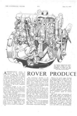
APPROXIMATELY similar in capacity to the Land-Rover petrol engine, the new Rover 2,052 c.c, four-cylindered oil engine announced yesterday has an identical maximum-power rating of 52 b.h.p. It is only 2 in. longer and about 70 lb. heavier than the conventional unit. It can therefore be installed in the 88-in. and 109-in, wheelbase chassis without modifications to the frame, suspension or transmission.
Land-Rover models at the 1956 Commercial Motor Show at Earls Court had a 2-in, extension of the wheelbase, which was introduced to accommodate the oil engine. The appearance of the vehicle is thus unchanged.
The oil engine increases vehicle prices by £100. The 88-in.-wheelbase model costs £715 and the 109-in, basic version £790 and de luxe model, £810.
A bore of 3 in. is combined in the 2-litre oil engine with a relatively short stroke of 3+ in., which gives a low piston speed at higher r.p.m. and enables inertia stresses to be reduced.
136
The combustion chamber is the Ricardo Comet Mk. 5 type, comprising a pre-combustion cell with a tangential throat and a double-leaf cavity in the piston crown. Fuel from a C.A.V. D.P.A. opposed-piston distributor pump i. supplied to pintaux nozzles giving main and auxiliary Jet sprays.
Located in line with the engine axis, the overhead valves are of the conventional side-by-side vertical type and are operated through short push-rods by a high-mounted chain-driven camshaft on the off side. The counterbalanced crankshaft is carried in three bearings, and both the main and big-end bearings are of the copper-lead steel-backed type with a tin overlay.
Wet liners of cast iron are employed, and the pistons are of low-expansion light alloy. The camshaft has four white-metal wrap-round bearings.
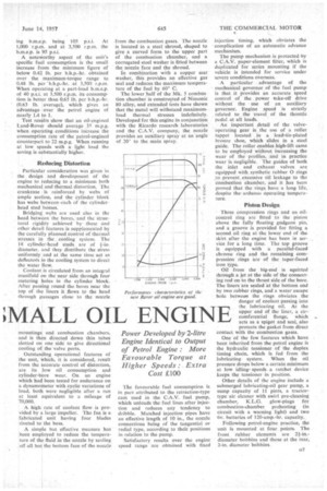
Whereas the petrol engine develops its maximum power at 4,000 r.p.m., the peak output of the oil engine is produced at 3,500 r.p.m. Performance curves show that a greater torque is provided by the oiler above a speed of 2,500 r.p.m. up to the maximum fullload governed speed, which represent road speeds of 37+ m.p.h. and about 52 m.p.h. respectively. The petrolengined Land-Rover is normally capable of a maximum speed of around 60 m.p.h.
This good torque characteristic at high speeds offsets the comparatively low maximum torque of 87 lb.-ft. at 2,000 r.p.m., which compares with a torque of 101 lb.-ft. developed by the petrol engine at 1,500 r.p.m. The rated torque of the oil engine is, however, substantially constant between 2,000 r.p.m. and 3,000 r.p.m., the correspond ing b.m.e.p. being 105 p.s.i. At 1,000 r.p.m. and at 3,500 r.p.m. the b.m.e.p. is 95 p.s.i.
A noteworthy aspect of the unit's specific fuel consumption is the small increase from the minimum figure of below 0.42 lb. per b.h.p.-hr. obtained over the maximum-torque range to 0.48 lb. per 'b.h.p.-hr. at 3,500 r.p.m. When operating at a part-load b.m.e.p. of 40 p.s.i. at 3,500 r.p.m. itsconsumption is better than 0.65 lb. per b.h.p.-hr. (0.63 lb. average), which gives an advantage over the petrol engine of nearly 1.4 to 1.
Test restilts show that an oil-cngined Land-Rover should average 35 m.p.g. when operating .conditions increase the consumption rate of the petrol-erigined counterpart to 22 m.p.g. When running at low speeds with a light load the saving is substantially higher.
Reducing Distortion
Particular consideration was given in the design and development of the engine to reducing to a minimum both mechanical and thermal distortion. The crankcase is reinforced by webs of ample section, and the cylinder block has webs between-each of the cylinder• head stud bosses. • Bridging webs are used also in the head between the bores, and the structural rigidity achieved by these and other detail features is supplemented by the carefully planned control of thermal stresses in the cooling system. The 18 cylinder-head studs are of 1-in. diameter, and they distribute the stress uniformly and at the same time act as deflectors in the cooling system to direct the water flow.
Coolant is circulated from an integral manifold on the near side through four metering holes in the cylinder block. After passing round the bores hear the top of the liners it flows to the head through Passages close to the nozzle mountings and combustion chambers, and is then directed down thin tubes slotted on one side to give directional cooling of the valve ports.
Outstanding operational features of the unit, which, it is considered, result from the accurate control of distortion, are its low oil consumption and cylinder-bore wear. On an engine which had been tested for endurance on a dynamometer with cyclic variations of load, both were negligible after a run at least equivalent to a mileage of 70,000.
A-high rate of coolant flow is provided by a large impeller. The fan is a fabricated unit having four blades riveted to the boss.
A simple but effective measure has been employed to reduce the temperature of the fluid in the nozzle by sealing off all but the bottom face of the nozzle
from the combustion gases. The nozzle is located in a steel shroud, shaped to give a curved form to the upper part of the combustion chamber, and a corrugated steel washer is fitted between the nozzle face and the shroud.
In combination with a copper seat washer, this provides an effective gas seal and reduces the maximum temperature of the fuel by 60° C.
The lower half of the Mk. 5 combustion chamber is constructed of Nimonic 80 alloy, and extended tests have shown that the metal will withstand maximumload thermal stresses indefinitely. Developed for this engine in conjunction with the Ricardo research laboratories and the C.A.V. company, the nozzle provides an auxiliary spray at an angle of 20° to the main spray.
The favourable fuel consumption is in part attributed to the retraction-type cam used in the C.A.V. fuel pump, which unloads the fuel lines -after injection and reduces any tendency to dribble. Matched injection pipes have an effective length of 10 in., the nozzle connections being of the tangential or radial type, according to their positions in relation to the pump.
Satisfactory results over the engine speed range are obtained with fixed injection timing, which obviates the complication of an automatic advance mechanism.
The pump mechanism is protected by C.A.V. paper-element filter, which is duplicated for series mounting if the vehicle is intended for service under severe conditions overseas.
A particular advantage of the mechanical governor of the fuel pump is that it provides an accurate speed control of the power +take-off drive without the • use of an auxiliary governor. Engine speed is strictly related to the travel of the throttle pedal at all loads.
An important detail of the valveoperating gear is the use of a roller tappet located in a lead-tin-plated bronze shoe, which slides in a steel guide. The roller enables high-lift cams to be employed without increasing the wear of the profiles, and in practice wear is negligible. The guides of both the inlet and exhaust valves are equipped with synthetic rubber 0 rings to prevent excessive Oil leakage to the combustion chamber, and it has been proved that the rings have a long life, despite thearduous operating temperature.
Piston Design Three compression rings and an oilcontrol ring arc fitted to the piston above the fully floating gudgeon pin, and a groove is provided for fitting a second oil ring at the lower end of the skirt after -the engine has been in service for a long time. The top groove is equipped with a parallel-faced chrome ring and the remaining compression rings are of the taper-faced iron type.
Oil from the big-end is squirted through a jet at the side of the connecting rod on to the thrust side of the bore. The liners are sealed at the bottom end by two rubber rings, and a water escape hole between the rings obviates the
• danger of coolant passing into the lubricating oil. At the upper end of the liner, a circumferential flange, which . acts as a spigot and seal, also protects the gasket from direct contact with the combustion gases.
One of the few features which have been inherited from the petrol engine is the hydraulic tensioner of the duplex timing chain, which is fed from the lubricating system. When the oil pressure drops below a certain minimum at low idling' speeds a ratchet device keeps the tcrisioner in position.
Other details of the engine include a submerged lubricating-oil gear pump, a sump capacity of 11 pints, a tractortype air cleaner with swirl pre-cleaning chamber, K.L.G. glow-plugs for combustion-chamber preheating (in circuit with a warning light) and two 6v. batteries of 120-amp.-hr. capacity.
Following petrol-engine practice, the unit is mounted at four. points. The front rubber elements are 21-in.diameter bobbins and those at the rear, 2-in, diameter bObbins.