


A NEW IDEA IN TIPPING GEARS.
Page 38
If you've noticed an error in this article please click here to report it so we can fix it.
A Résumé of Recently Published Patents.
The powei• to operate the tipping gear which 35 described in specification No. 162,374 is derived from the tractor, which needs simply to be reversed a few inches • in order to tip the body of the trailer either to the side or to the 'rear, according to the design of the mechanism.
As is indicated to some eatent by the foregoing, the gear is applicable to a trailer. A four-wheeler is shown, in the drawing which accompanies the specification, of that type in which the front aale.sopporta the fore end of the vehicle on a turntable, or, as it is sometimes called, a fifth wheel,The frame of the chassis of this trailer is built of steel channels with the flanges inturned. The fore-carriage of the trailer is of the usual type, except that, instead of the upper portion being positively securedito the frame of the vehicle, it is made as a separate and distinct part, and so designed that it will slide inside the-channel frame of the trailer. In order that its movements may be facilitated, it is fitted on the top, bottom, and sides with rollers, which themselves make contact with the metal of the channel. It will be understood that, as the tractor is reversed, it will, in the first place, cause this sliding fore-carriage to move towards the rear of the trailer. It is this movement which effects the tipping of the trailer body.
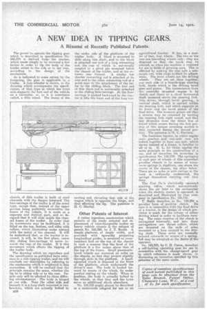
The drawing which we reproduce and the specification as.published have reference to a side-tipping traileraand we will conclude our clestiltinn by reierring to the mechanism which is employed in this connection. It will be realized that the principle remains the same, whether the tip be to either side or to the rear. Details only will be affected by these differing circumstances. The body is hinged at one side. Near the other side and beneath it is a long shaft mounted in two brackets, which are actually bolted to
a38
the under side of the platform of the trailer body. A block is mounted to slide aloiig this shaft, and to the block is attached one end of a long connecting -rod, the rear of which is universally coupled to a pivot pin mounted below the chassis of the trailer, and at the extreme rear thereof. -A similar -but shorter connecting rod is attached at its rear end to the other coanecting rod at a point near to the attachment of the latter to the sliding bleak. The fore end of this short rod is universally attached to the sliding fore-carriage. As the forecarriage is nushed backward by the tractor it lifts the front end of the long Con
fleeting rod, elevating that side of the wagon which is opposite the hinge, and thus effecting the tip. The patentee is H. C. Manley.
Other Patents of Interest.
A rather ingenious construction which permits of the ready removal and replacement of interchangeable bodies on heavy vehicle chassis isthe subject of patent No. 162,393, by J. T. Booth. A simple platform, of ample width, and provided with upwardly projecting longitudinal guides, is mounted on crossmembers laid on the tap of the chassis in such a manner that the level of the platform is a few inches above that of the top of the frame. Small pneumatictyred wheels are mounted on axles on the chassis, so that they project slightly through slots in the platform. A hand. operated winch is disposed at the front of the platform, about underneath the driver's seat. The body is hauled forward by means of the winch, its under portion resting on the wheels. When in position, the body is actually bolted to the wheels, so that they and the tyres serve as additional shock absorbers.
No. 154,552 might almost he described as a motorcycle adapted for use as an agricultural tractor. It has, as a matter of fact, four wheelS. The two at the rear are travelling wheels only they are disposed so that the track may be altered, as when the machine is required for use in fields of growing corn. This ii effected by making the rear aXle a telescopic one, with stops to limit its adjust:dent. The front wheels are the driving
wheels. They are set close together, one earls side of a bicycle-type steering fork, inside which is the driving • bevel gear and pinion. The transmission from the centrally mounted engine is by clutch and chain to a short horizontal shaft mounted above the steering fork. This drives, through bevel gearing, a .vertical shaft, which is carried within the steering fork and which supports at its lower end die bevel pinion of the final drive. The inventor points out that a reverse may be obtained by turning the steering fork right round, and that any diversion from the direct line of travel which occurs during the first portion di this unique reversing motionis duly corrected during the second portion. The patentee is G. C, Davison.
The frameless tractor, in which engine ease,, gearbox, and rear-axle case are bolted together to form one unit, which serves instead of a frame, is familiar to all of us. If. L. Le Grain applies the same principle to the construction of a car, arid he deseribes his invention in , specification No. 152.979. The Springing of each pair a wheels of this somewhat peculiar chassis i5 by means of transverse springs in duplicate,-one above the centre of the chassis, the other below: There are no axles or axle casings as the term is ordinarily understood, the springs themselves carrying out that duty.
The Fiat Co.'s electrically operated starting valve,which automatically closes the air inlet to the carburetter -when the electric starter is operated, is described and illustrated by that company _in specification No. 155,795. T. Ballu describes in No. 129,986 a peculiar form of positive clutch. . He uses it in connection with the final drive of a tractor, in the design of which provision is made for the release of either driving Wheel in order to facilitate turning. The outer member of the clutch is corrugated internally, and into these corrugations 'are thrust rollers, which are mounted on the ends of arms mounted on a boss secured to the driving shaft. These arms are normally pressed outward by means of a spring, bul may be retraaed at the desire of the operator.
No. 162,335, by C. H. Caton, describes a self-locking operating gear for use in connection with the change-speed gear to which reference is made above, in discussing an invention specified by this patentee of the same name.