SIMPLE MECHANICS
Page 74

If you've noticed an error in this article please click here to report it so we can fix it.
Gear ratios a compromise
by Preceptor
THE GEAR ratios chosen for gearboxes are something of a compromise. For example, for rapid acceleration in top gear a lower ratio is required than the one best suited for fuel economy on long level stretches of road. Obviously, the more gear ratios available to a skilled driver, the less of a compromise is the one he will choose for a particular circumstance.
A -splitter' gearbox is designed with this problem in mind and provides double the choice of gear ratios available from a gearbox. In one type of -splitter.' box, instead of there being one pair of constant mesh gears taking the drive from the primary or clutch shaft to the layshaft, there are two pairs providing alternative gear ratios which may be chosen by the driver at will.
Typical ratios obtained on a Leyland gearbox of this type are Low 1st 9.352 1 Low 2nd 5.764 1 Low 3rd 3.5521 Low 4th 2.147 1 Top 1 1 1st 6.988 1 2nd 4.308 1 3rd 2.655 1 4th 1.605 1 Overdrive 0.76 1
Another type of "splitter'. box provides the additional gear ratios by fitting the extra gears at the rear end of the box instead of at the front.
It is essential on all
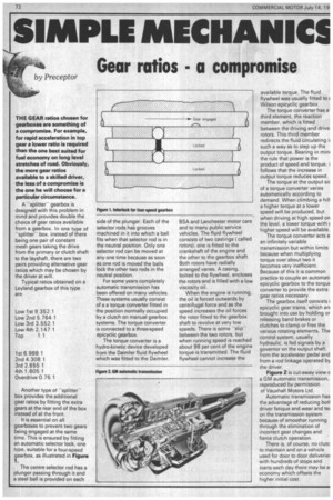
gearboxes to prevent two gears being engaged at the same time. This is ensured by fitting an automatic selector lock, one type, suitable for a four-speed gearbox, as illustrated in Figure 1.
The centre selector rod has a plunger passing through it and a steel ball is provided on each
side of the plunger. Each of the selector rods has grooves machined in it into which a ball fits when that selector rod is in the neutral position. Only one selector rod can be moved at any one time because as soon as one rod is moved the balls lock the other two rods in the neutral position.
For some years completely automatic transmission has been offered on many vehicles. These systems usually consist of a a torque converter fitted in the position normally occupied by a clutch on manual gearbox systems. The torque converter is connected to a three-speed epicyclic gearbox.
The torque converter is a hydro-kinetic device developed from the Daimler fluid flywheel which was fitted to the Daimler, BSA and Lanchester motor cars and to many public service vehicles. The fluid flywheel consists of two castings ( called rotors); one is fitted to the crankshaft of the engine and the other to the gearbox shaft. Both rotors have radially arranged vanes. A casing, bolted to the flywheel, encloses the rotors and is filled with a low viscosity oil.
When the engine is running, the oil is forced outwards by centrifugal force and as the speed increases the oil forces the rotor fitted to the gearbox shaft to revolve at very low speeds. There is some "slip" betweenthe two rotors, but when running speed is reached about 98 per cent of the engine torque is transmitted. The fluid flywheel cannot increase the available torque. The fluid flywheel was usually fitted to E Wilson epicyclic gearbox.
The torque converter has a third element, the reaction member, which is fitted between the driving and drive rotors. This third member redirects the fluid circulating ii such a way as to step up the output torque. Bearing in min( the rule that power is the product of speed and torque, i follows that the increase in output torque reduces speed.
The torque at the output sic of a torque converter varies automatically according to demand. When climbing a hill a higher torque at a lower speed will be produced, but when driving at high speed on the level, a lower torque with C higher speed will be available.
The torque converter acts a an infinitely variable transmission but within limits because when multiplying torque over about two it becomes very inefficient. Because of this it is common practice to couple an automati epicyclic gearbox to the torque converter to provide the extra gear ratios necessary
The gearbox itself consists ( epicyclic gear trains, which arc brought into use by holding or releasing band brakes or clutches to clamp or free the various rotating elements. The control system, usually hydraulic, is fed signals by a governor on the output shaft, from the accelerator pedal and from a rod linkage operated by the driver.
Figure 2 is cut-away view e a GM automatic transmission, reproduced by permission of Vauxhall Motors Ltd.
Automatic transmission has the advantage of reducing botl driver fatigue and wear and teE. on the transmission system because of smoother running through the elimination of incorrect gear changes and fierce clutch operation.
There is, of course, no clutc to maintain and on a vehicle used for door to door deliverie with hundreds of stops and starts each day there may be al economy which offsets the higher initial cost.


