


AIR SUSPENSION WILL AFFECT TYRE DESIGN
Page 72
Page 73
If you've noticed an error in this article please click here to report it so we can fix it.
THE part that pneumatic tyres play in the suspension of a road .vehicle is likely to decrease with the advent of air-suspension systems, thereby enabling tyres to be put to their correct use of providing traction. This was one of the conclusions drawn by Mr. J. H. Sainsbury, development engineer of the Firestone Tyre and Rubber Co„ Ltd., in a paper which was presented in London to the Automobile Division of the Institution of Mechanical Engineers on Tuesday.
In his payer Mr. Sainsbury traced briefly the development of vehicle airsuspension systems, pointing out that since 1906 several patents have been granted for designs using air as a suspension medium for both passenger and commercial vehicles, but that it was not until the early 1930s that this form of suspension was given serious -consideration.
In January, 1936, a paper presented tc the American Society. of Automotive Engineers, by Mr. Roy W. Brown, gave details of an investigation into the application of air springs to a passenger car, the vehicle used being a Plymouth saloon.
The interesting thing about this vehicle was that the suspension units used were of the two-convolution type, not unlike the type currently in use in the United States and Europe.
The automobile industry's enthusiasm during the 1930s did not come up to that of air-suspension designers, however, and it was only since the last war that this type of suspension had become established, principally through the efforts of coach manufacturers and operators in the U.S.A.
Initially, the two-convolution circular spring was considered desirable because it gave the most compact shape . for a given volume; a circular form lent itself readily to mass production; and with a circular shape it was possible to maintain a uniform cross-section considered desirable to give a good flex life.
The type of bellows in common use n38 today consisted of a rubber-andfabric moulding, with a central steel girdle ring to restrict radial expansion. and a steel bead ring at each end incorporating bolts for attachment to the sprung and unsprung parts of the vehicle.
Bellows were normally de signed to operate at 65-75 p.s.i. for maximum static load, but as the normal air pressure available on an air-braked vehicle was at
ENT least 80-85 p.s.i., a satisfactory
allowance must he made for overloading and the maximum recommended pressure for most designs was 100 p.s.i. for. static loading, giving a safety . factor of approximately 5 to 1 against the bursting pressure. There was no minimum specified pressure; satisfactory operation had been achieved with pressures down to 2 p.s.i. . .
A frequency of 80-85 cycles per minute was the minimum attainable with this type of spring, which, the author stated. was acceptable by the present standard of commercial-vehicle application, although Mr. Sainsbury went on to mention that in his contact with vehicle manufacturers there seemed to be differences of opinion as to the optimum wheel frequency for commercial-vehicle application.
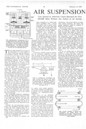
Two types of air springing installed were discussed in the paper; direct-acting installation, in which the spring load was equal to the wheel load; and trailing-arm installation, in which the 'spring load was less than the wheel load.
With the direct-acting installation there were usually four air bellows to each axle, these being carried on platforms mounted on the axles, and each pair of springs being connected by a surge tank. The volume of the surge tank in relation to the volume of the springs determined the rate and frequency characteristics of the installation. By correct choice of surgetank volume, however, the wheel and spring frequency could be reduced to 80-85 cycles per minute.
Each of the surge tanks was connected via a levelling valve (or valves) to the main air reservoir, a check valve being fitted between the tanks to ensure an ample supply of air for braking in the unlikely event of a failure occurring in the suspension circuit. The levelling valves were principally employed to maintain the same vehicle height above the ground irrespective of thestatic load, and incorporated a hydraulic device to. give a delay of several :seconds before the bellows .pressUres were adjusted. There-fore the air expanded and compressed under .approximate adiabatic conditions. when riding over normal road'irregularities .
• As an air spring, had no horizontal stability, it was necessary tol provide means for locating the axles relative to the chasSis: this entailed the use of radius rods and Panhard rods, preferably rubberbushed to dispense with lubrication.
Similarly, as the suspension system was almost frictionless, double-acting dampers Were necessary to dampen vertical Movement, and bump rubbers and rebound straps were desirable to prevent over-compression or extension of the bellows when running over rough surfaces.
With a trailing-arm installation, two bellows units per axle were sufficient, and if the trailing arms were curved outwards so that the transverse centres of the springs were equal to the track of the tyres, the increased lateral spacing gave improved roll stability. If hollow trailing arms were used, they could be employed as the surge tanks.
As distinct from the direct-acting layout, the wheel frequency could differ from the spring frequency by adjustment. of the distance between the axle and the spring centre lines relative to the trailing arm pivot points. Thus, assuming that a wheel frequency of 95 cycles per minute was required, this could be obtained with 80-85 cycles per minute springs by adjusting the leverage ratio to the order of 1.41 to 1 (in the accompanying a diagram).
In dealing with the theory of air springs, the author discussed the effect that alteration in the volume of the surge tank had upon spring rate and frequency. Thus, assuming a bellows volume of 590 Cu. in. with no surge tank, the rate would be 1,700 Ib./in. and the frequency 107 cycles per minute: with a 1,770-cu.-in. surge tank the rate became 900 lb./in. and the frequency 79 cycles per minute: whilst with a 3,540-cu.-in, surge tank the rate was 760 111./in, and frequency 73 cycles per minute. A 1,770-cu.-in. surge tank was considered to be the practical limit for such a tank from size considerations.
Mr. Sainsbury, referring to service experience, quoted the case of American coaches having been operated for 600,000 to 700,000 miles without any failure of the' air springs, whilst the average life of a set of steel springs under the same conditions was about 125,000 miles.
Tests on Belgium pave made with a tractor unit had shown it possible to travel 5,000 miles over such surfaces without damage, whereas comparable vehicles with steel springs had sustained cab and bodywork damage after 2,000 miles.
Other comparisons made were that whereas the normal steel spring had a nearly constant rate, an air spring approached the idea by having a variable rate, the operating pressures being automatically adjusted by the levelling valves.
Conversely, whereas the steel spring gave a high frequency with light loadings, and this frequency reduced as the load was increased, an air spring gave constant frequency characteristics irrespective of the load.
The friction in a leaf spring, although possessing the advantage of self damping, was also responsible for transmitting high-frequency vibrations from the road to the bodywork, these being eliminated with air springs. Similarly tyre, brake and wheel noises transmitted to the body were reduced by the use of air springs
Air springs also provided the advantage of a constant loading height, this being particularly important on public service vehicles and goods vehicles which regularly used loading bays.
A disadvantage of air springs, however, was that because they had no horizontal stability locating rods were required between the axle and the chassis frame, these being unnecessary with leaf springs.
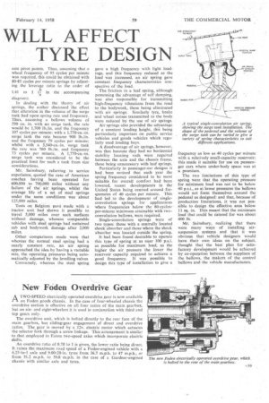
Particularly in passenger-ear designs it had been noticed that each year the spring frequency considered to be most suitable for overall comfort had been lowered, recent developments in the United States being centred around frequencies of 40 cycles per minute. This had led to the development of singleconvolution springs for applications where frequencies below the 80-cyclesper-minute minimum attainable with twoconvolution bellows, were required_
Single-convolution springs were of two types: those with a centrally located shock absorber and those where the shock absorber was located outside the spring.
It had been found desirable to operate this type of spring at as near 100 p.s.i. as possible for maximum load, as the higher the air pressure the lower the reservoir capacity required to achieve a good frequency. It was possible to design this type of installation to give a frequency as low as 40 cycles per minute with a relatively small-capacity reservoir: this made it suitable for use on passsenger cars where under-body space was at a premium.
The two limitations of this type of spring were that the operating pressure for minimum load was not to be below 40 p.s.i., as at lower pressures the bellows would not form themselves around the pedestal as designed: and that, because of production limitations, it was not possible to design the effective area below 11 sq. in. This meant that the minimum load that could be catered for was about 400 lb.
Mr. Sainsbury, realizing that there were many ways of installing airsuspension systems and that it was obvious that vehicle designers would have their own ideas on the subject, thought that the best plan for satisfactory development would be achieved by co-operation between the suppliers of the bellows, the makers of the control bellows and the vehicle manufacturers.