


A Control Valve for Powered Steering pATENT No. 759,163 (Clayton
Page 72
If you've noticed an error in this article please click here to report it so we can fix it.
Dewandre Co., Ltd., Titanic Works. Lincoln) shows a power-assisted steering system. The basis of the patent is a novel means for operating the control valve of the hydraulic system. A continuously running pump circulates oil around a circuit which, if it be
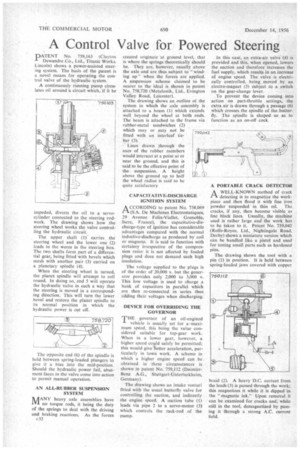
impeded, diverts the oil to a servocylinder connected to the steering rodwork. The drawing shows how the steering wheel works the valve controlling the hydraulic circuit..
The upper shaft (I) carries the steering wheel and the lower one (2) leads to the worm in the steering box. The two shafts form part of a differential gear, being fitted with bevels which mesh with another pair (3) carried on a planetary spindle (4).
When the steering wheel is turned, the planet spindle will attempt to roll round. In doing so, end 5 will operate the hydraulic valve in such a way that the steering is moved in a corresponding direction. This will turn the lower bevel and restore the planet spindle to its normal position in which the hydraulic power is cut off.
The opposite end (6) of the spindle is held between spring-loaded plungers to give it a bias into the mid-position. Should the hydraulic power fail, abutment faces in the valve come into action to permit manual operation.
AN ALL-RUBBER SUSPENSION SYSTEM
hAANY heavy axle assemblies have IVI no torque rods, it being the duty of the springs to deal with the driving and braking reactions. As the forces
(32 created originate at ground level, that is where the springs theoretically should be. They are, however, usually above the axle and are thus subject to "winding up' when the forces are applied. A suspension scheme claimed to be nearer to the ideal is shown in patent No. 758,720 (Metalastik, Ltd., Evington Valley Road, Leicester).
The drawing shows an outline or the system in which the axle assembly is attached to a beam (1) which extends well beyond the wheel at both ends. The beam is attached to the frame via rubber-metal sandwiches (2) which may or may not be fitted with an interleaf tiebar (3).
Lines drawn through the axes of the rubber members would intersect at a point at or near the ground, and this is said to be the effective point of the suspension. A height above the ground up to half the wheel radius is said to be quite satisfactory CAPACITATIVE-DISCHARGE IGNITION SYSTEM
ACCORDING to patent No. 758,069 (S.A. De Machines Electrostatiques, 29 Avenue Felix-Viallet, Grenoble, .Isere, France), the eapacitative-discharge-type of ignition has considerable advantages compared with the normal inductive-discharge as produced by coil or magneto. It is said to function with certainty irrespective of the compression ratio: it is not affected by fouled plugs and does not demand such high insulation.
The voltage supplied to the plugs is of the order of 20,000 v. but the generator provides only 2,000 to 3,000 v. This low voltage is used to charge a bank of capacitors in parallel which are then re-connected in series thus adding their voltages when discharging.
DEVICE FOR OVERRIDING THE GOVERNOR
THE governor of an oil-engined
vehicle is usually set for a -maximum speed, this tieing the value considered suitable for top-gear work. When in a lower gear, however, a higher speed could safely be permitted; this would give better acceleration, particularly in town work. A scheme in which a higher engine speed can be obtained in these circumstances is shown in patent No. 759,112 (DaimlerBenz A.G., Stuttgart-Unterturkheim, Germany).
The drawing shows an intake venturi fitted with the usual butterfly valve for controlling the suction, and indirectly the engine speed. A suction tube (1) leads via pipe 2 to a servo-motor (3) which controls the rack-rod of the pump.
In this case, an extra-air valve (4) is provided and this, when opened, lowers the suction and therefore increases the fuel supply, which results in an increase of engine speed. The valve is electrically controlled, being moved by an electro-magnet (5) subject to a switch on the gear-change lever.
To prevent the device coming into action on part-throttle settings, the extra air is drawn through a passage (6) which crosses the spindle of the butterfly. The spindle is shaped so as to function as an on-off cock A PORTABLE CRACK DETECTOR
PAA WELL-KNOWN method of crack detecting is to magnetize the work piece and then flood it with fine iron powder suspended in thin oil. The cracks, if any, then become visible as fine black lines. Usually, the machine used is rather large and the work has to be taken to it. Patent No. 759,042 (Rolls-Royce, Ltd., Nightingale Road. Derby) shows a miniature version which can be handled like a pistol and used for testing small parts such as hardened pins.
The drawing shows the tool with a pin (1) in position. It is held between spring-loaded jaws covered with copper braid (2). A heavy D.C. current from the leads (3) is passed through the work; this magnetizes it while it is dipped in the "magnetic ink." Upon removal it can be examined for cracks and, while still in the tool, demagnetized by passing it through a strong A.C. current field.