


A Ford Half-track for Tractors
Page 62
If you've noticed an error in this article please click here to report it so we can fix it.
vide 'crawler tracks for the ,1
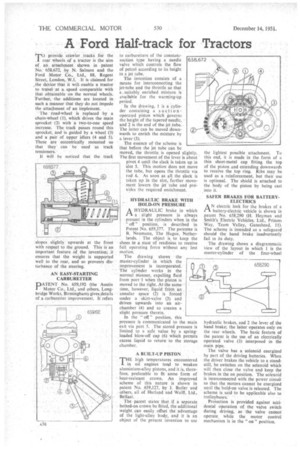
rear wheels of a tractor is the aim of an attachment shown in patent No 658,6-72; by N. Salmon and the Ford Motor Co., Ltd., 88, Regent Street, London, WA. It is claimed for the device' that it will enable a tractor to travel at a. speed comparable with that obtainable on the normal wheels. Further, the additions are located in such a manner that they do not impede the attachment of an implement.
The• road-wheel is replaced by a chain-wheel (1), which drives the main sprocket (2) with a two-to-one speed increase. The track passes round this sprocket, and is guided by a wheel (3) and a pair of upper idlers (4 and 5), These are eccentrically mounted so that they can be used as track tensioners.
It will be noticed that the track slopes slightly upwards at the front with respect to the ground. This is an important feature of the invention; it ensures that the weight is supported well to the rear, and so prevents disturbance of the steering.
AN EASY-STARTING CARBURETTER DATENT No. 659,192 (the Austin Motor Co., Ltd., and others, Longbridge Works, Birmingham) gives details of a carburetter improvement. It refers
to carburetters of the constantsuction type having a needle valve which controls the flow of petrol according to its height in a jet tube.
The invention consists of a means for interconnecting the jet-tube and the thrattle so that a .suitably, enriched mixture is available for the warming-op period.
In the drawing, 1 is a cylin
der containing a ion onoperated piston which governs the height of the tapered needle, and 2 is the end of the jet tube. The latter can be moved downwards to enrich the mixture by a lever (3).
The essence of the scheme is that before the jet tube can be moved, the throttle is opened slightly.
The first Movement of the lever is about pivot 4 until the slack is taken up in slot 5. This motion does not move the tube, but opens the throttle via rod 6. As soon as all the slack is taken up in the slot, further movement lowers the jet tube and pro
vides the required enrichment. .
HYDRAULIC BRAKE WITH HOLD-ON PRESSURE A HYDRAULIC brake in which PA. a slight pressure is always
• present in the cylinders when in the
off" position, is described -in Patent No. 659,377. The patentee is 13, Neumann, The Hague, Netherlands. The object is to keep the shoes in a state of readiness to receive full operating force without any lost motion.
The drawing shows the master-cylinder in which the improvement is incorporated. The cylinder works in the normal manner, expelling fluid from port I when the piston is moved to the right. Atahe sainetime, however, liquid frem an annular space (2) is forced under a skirt-valve (3) and driven upwards into an airchamber (4) and so creates a slight pressure therein.
In the " off " position, this pressure is communicated to the main exit via port 5. The stored pressure is limited to a safe value by a springloaded blow-off cap (6) which permits excess liquid to returnto the storage chamber,
A BUILT-UP PISTON
THE high temperatures encountered in oil engines tend to weaken aluminium-alloy pistons, and it is, therefore, preferable to fit some form of heat-resistant crown. An improved scheme of this nature is shown in patent Na. 659,127, by J. Butler and others, all of Harland and Wolff, Ltd.,
Belfast. , The patent states that if a separate bolted-on crown be fitted, the additional weight can easily offset the advantage of the light-alloy body, and it is an object of the present invention to use the lightest possible attachment. To this end, it is made in the form of a thin sheet-metal cap fitting the top of the piston and extending downwards to receive the top ring. Ribs may be used as a reinforcement, but their use is optional. The shield is attached to the body of the piston by being cast into it.
SAFER BRAKES FOR BATTERYELECTRICS
AN electric lock for the brakes of a battery-electric vehicle is shown in patent No. 658,290 (H. Heyman and Smith's Electric Vehicles,. Ltd., Princes Way, Team Valley, Gateshead, 11). The scheme is intended as a safeguard should the hand brake inadvertently fail in its duty.
The drawing shows a diagrammatic view of the layout in which I is the master-cylinder of the four-wheel
hydraulic brakes, and 2 the lever of the hand brake; the latter operates only on the rear wheels. The basic feature of the patent is the use of an electrically operated valve (3) interposed in the main pipe.
The valve has a solenoid energized by part of the driving batteries. When the driver brakes the vehicle to a standstill, he switches on the solenoid which will then close the valve and keep the brakes in the on position. The solenoid is interconnected with the power circuit so that the motors cannot be energized until the hold-on valve is released. The scheme is said to be applicable also to trolleybuses_
Protection is provided against accidental operation of the valve switch during driving, as the valve cannot operate while the motor control mechanism is in the " on " position.