


Patents Completed.
Page 20
If you've noticed an error in this article please click here to report it so we can fix it.
Complete specifications of the following patents will be sent to any address in the United Kingdom upon receipt of eightpence per copy at the Sale Branch, Patent Office, Holborn, W.C.
ROLLED GE...ill TEET11.—Anderson.—No. 557, dated 9th January, 1911. —This invention relates to mechanism for forming gear teeth by rolling them on a blank. The blank is clamped between two discs and treated first by breaking-down rollers and then by finish ing rollers. The principal features of the present invention lie in the means for supporting and rotating the blank and in the construction and arrangement of the rollers. A plate rests upon the base and is adapted to oscillate slightly on it, the pivot being such as to permit longitudinal adjustment of the plate and lateral adjustment of both pivot and plate. This lateral adjustment is obtained by a hand wheel and screw, by which the blank is fed towards the particular roller required. The gearing is SD arranged that the blank is driven at a speed neither a factor nor a multiple of that of the rollers, thereby operating upon each tooth in the blank by successively-different teeth of the rollers. It is also desirable when finishing the process to reverse the direction of rotation.
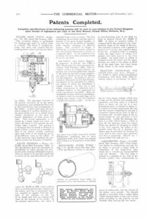
VALVE GEARING. — Moore.—No. 27,225, dated 23rd November, 1910.-1n this specification there are described improvements in valve gearing for fourstroke-cycle internal-combustion engines. They are stated to be specially applicable to valves of the type described in specifi
cation No. 20,746 of 1909. where a sleeve valve is located between the cylinder and the piston, and has a single.port opening, adapted to register with the inlet port of the cylinder at the top of its stroke and with an exhaust port when at the bottom of its stroke. In the present construction, the valve is
operated from a main eccentric. The link connecting the eccentric and the valve is formed in two parts hinged together, so that the link can be flexed or straightened, thereby changing its effective length. This variation in length is effected by a second eccentric, which in the construction illustrated is shown on a separate shaft. In the preferred construction, however, both eccentrics would be on the one shaft.
MAGNETO.– Mea Fabrik Magnet— E. Apparate. 4,085 of 1911, dated under the International Convention, 17th February, 1910.—This inveution relates to magneto-electric apparatus for internal-combustion engines of the kind having bell-shaped magnets, one end of which serves as the bearing for the armature. According to the construction illustrated in this specification. the magnet can be oscillated in a stationary casing to which the distributer is rigidly attached. In this way a very stable construction is obtained and a complete balance of the apparatus for every adjustment is possible. Since the distributer is fixed there is no possibility, as there is with the movable type, of its coming into contact with hot cylinders or pipes and causing trouble. In the cas ing there is pivotally mounted a normal bell-magnet comprising one or more superposed bells, and inside the magnet there rotates an H-armature of the usual type.
REINFORCED INNER TUBES.— Hall.—No. 16,189, dated 13th July, 1911. —This specification relates to the mane facture of reinforced inner tubes for pneumatic tires and describes a method
of manufacturing tires of the kind set forth in Letters Patent No. 28,666 of 1909. A sheet of uncured rubber is wrapped about the mandrel of the crosssectional shape of the inside of the tire. This mandrel is formed with a groove or grooves on it to give the required shape to the tire. A band of fabric is wrapped round the inner layer of rubber and pressed into these grooves in the form of pleats. An outer layer of rubber is wrapped round the fabric and the space between the sides of the pleats is filled up at the same time, the whole being finally baked in the usual manner.
DRAINING MECHANISM FOR CRANK PITS.—Soc. Anon. Peugeot.— No. 12,487-11, dated under International Convention, 11th June, 1910.—This invention relates to mechanism for drain ing oil from engine casings, which may or may not he divided into several compartments, and from which it is desired either to drain out the oil to a predetermined level or entirely to empty it. A conduit is formed underneath the case and the various compartments are put in connection therewith by holes in the intervening wall. Overflow pipes of the required height. are also provided in each compartment-. Inside the drainage conduit is a tube which forms a valve to close all the openings from the casing. These are opened by bringing an orifice in the valve opposite the orifice in the conduit when the oil is drained out. Means may be provided for locking the valve tube in the various open positions, and this is preferably effected by a spring-loaded ball and grooves.
CARBURETTER.—Poppe.—No.1,316, dated 18th January, 1911.—This invention relates to carburetters and has for its object to provide a simple form of carburetter of the eingle-lever type which has a variable-jet interconnected with the throttle. The fuel inlet is formed in a passage in one wall of the throttle conduit and communicates by means of radial holes with the interior of the hollow valve spindle. The throttle spindle is provided with a radial outlet which registers more or less with a cover plate according to the position of the throttle, thus varying the fuel outlet.