


Suction-amplified Hydraulic Brake
Page 58
If you've noticed an error in this article please click here to report it so we can fix it.
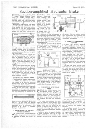
FROM Clayton Dewandre Co., Ltd., Titanic Works, Lincoln, comes patent No. 693,842, dealing with a modified form of suction-assisted hydraulic brake. The aim of the design is to simplify the Construction of such mechanisms.
Referring to the drawing, the pedaloperated hydraufie cylinder (I) leads, via a flexible pike (2) to the tubular piston-rod (3) Of the servo-cylinder. Fluid from thepedal cylinder passes through this rod, lifts a one-way valve (4) and enters the main hydraulic cylinder 5) from which the brakes are powered. So much is the unassisted action, which must of course be operative at all times.
The power assistance is brought into play in the following, way: When the pedal is depressed, part of the fluid causes downward movement of a plunger valve (6). The action of this • is first to close the atmospheric port by pulling down a seating on to a disc valve (7).
Further movement then pulls the disc • valve down off the suction port (8) thereby permitting suction to take effect in the servo-cylinder via pipe 9. The servo-piston (10) is then moved leftwards, dosing the one-way valve (4) and creating a working pressure in the main hydraulic cylinder.
LIGHT-ALLOY PISTON RINGS THE suggestion is made in patent No. 693,501, that lightness in a piston ring might be h desirable property, having regard to the high accelerations imparted to it during running.
The patent shows a piston ring made mainly of light alloy, with a steel ring embedded in it to provide resilience. Alternatively, as shown in the drawing, the alloy ring may be grooved in its bore to receive sepafate sPring-steel ring (1). In alt cases, the wearing surfaces of the ring are given an electrodeposited layer of chromium. The patentee is E. Mahle, 3 Rappweg, Stuttgart N., Germany.
A CLOSED-CIRCUIT ENGINECOOLING SYSTEM AN engine-cooling system employing higher temperatures than normal, is disclosed in patent No. 693,873, by ,1/440
Daimler-Benz A.G., Stuttgart Untertiirkbeim, Germany. The system employs a closed circuit, and boils the cooling liquid, which is condensed in a normal type of radiator.
The drawing shows the layout of the scheme in which 1 is a storage tank, 2 a pump and 3 the radia tor. A feature of the arrangement is the provision of a spring-loaded safetyvalve (4) which, if excessive pressure be developed, operates to close a throttle valve (5) to which it is linked. This slows down the engine, and works an indicating device.
No mention is made of the liquid employed, except a statement that it is frost-proof. No topping-up is needed, because there is no escape path for any liquid or vapour.
TUBELESS TYRES
FROM the B. F. Goodrich Co., 230 I Park Avenue, New York, U.S.A., comes patent No. 694,294. This shows a tyre of the tubeless type, that is, one in which the air is pumped directly into the outer cover. The patent suggests that in order to prevent leakage, the inner surface be given a thin coating of butyl rubber, which is more impermeable than the natural variety.
A COIL-SPRING UNIVERSAL JOINT DATENT No. 693,844, comes from
the Dunlop Rubber Co., Ltd„ 1 Albany Street, London, N.W.1, and shows a universal joint in which the resilient member is a steel coil-spring. The joint is specifically intended for use between gearbox and propeller shaft.
Two metal end-members are used; these are conically bored on their inner sides to receive conical plugs (1). The plugs, which can b," pulled up by screws (2) firmly grip the ends of a four-start coil-spring (3), which constitutes the power-transmitting member of the unit.
Inside the spring the spaee is filled by a solid cylindrical plug (4) of soft rubber, whilst the outer surface of the spring is covered by a protective tube A GERMAN AIR-COOLED • ENGINE
PATENT No. 693,828 (Klockrie Humboldt-Deutz A.G., Cologn Germany), discloses a design for •a engine provided with forced air-coolin The scheme is principally intended f( multi-cylindered V-type engines.
The cooling fan is located in It space between the two rows ( cylinders, and the drawing shows a se. lion through this central plane. Ti air intake (1) is at the front, where fan (2) is located. This forces, powerful draught of air over the finne cylinders, which are enclosed in ti casing.
The shaft that drives the fan is title at its rear end with a charging blow (3) which gets its air supply from thi which has been warmed by passing ota the cylinders. and delivers it to ti intake of the engine.
The two fans are driven 'by gearir (4 and .5) from the crankshaft. Ti intermediate shaft (6) is of sma diameter, so that it can act as a torsin rod to smooth out sudden spec variation.
A centrifugal clutch (7) is inco. porated in the drive; although th comes into operation almost as soon the engine runs, it nevertheless protec the fan assembly from the initii acceleration during the first few firin strokes.