


Rubber-spring Mounting
Page 36
If you've noticed an error in this article please click here to report it so we can fix it.
Obviates Need for Shackles
A Résumé of Recently Published Patent Specifications
USING leaf springs, 'which, at normal loading, are in a practically flat state, is a popular practice, because, in such circumstances, the change of length during deflection is at a minimum, and can be much more conveniently accommodated by . the resilience of a rubber block than by the conventional pin-and-shaekle method.
Such is the view of the Dunlop Rubber Co., Ltd., Albany Street, London, which discloses, in -conjunction with S. Sadler, in patent No. 545,841, a design for a spring mounting, which is claimed to be superior to the type employing rubbei=bushed shackles, in that it snore readily permits twisting of the spring.
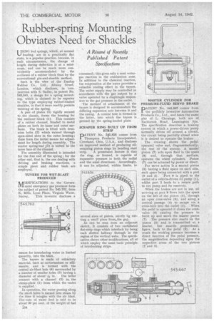
A pair of plates (4) rigidly secured to .the chassis, forms the housing for the resilientthlock (1). This consists of a rubber channel, honded to metal plates on both its inner and outer surfaces. The block is fitted with trunnion bolts. (2) which extend through open-sided slots in the outer housing; these form the initial means for adjustment for length during assembly. The • master spring-leaf (3) is bolted to the inner face of the channel.
The assembly illustrated is intended for the free end of the spring; for the other end, that is, the one dealing with driving and braking reactions, a simple pivot and rubber bush .are employed. , TUYERE FOR WET-BLAST PRODUCER NAODIFICATIONS to the Government emergency gas producer form , the subject of patent No 545,762, from K. Mills, Lyne Place, Virginia Water, Surrey, This inventor discloses a means for introducing water in limited quantity, into the blast.
The tuyere is made of refractory material, such as carbortindum or sillimanite, and is formed with the central air-blast hole (4) surrounded by a number of smaller holes (3) having a
diameter of about -FL, in. The latter connect with a channel (2) in. the clamp-plate (1) from which the -water is supplied.
In operation, the water passing along the small holes is turne.d into steam by the time it mingles with the air blast. The rate of water feed is said to be about 50 per cent, of the weight of fuel 134 consumed; this gives only a semi watergas reaction in the combustion zone. In addition to the chemical reaction, the evaporation of the water provides a valuable cooling effect in the tuyere. The water supply may be controlled in accordance with the gas output by a valve operated by a diaphragm responsive to the gas pressure in the outlet.
The method of attachment of the tuyere is designed to accommodate the differing expansion rate between it and the casing. A conical hole is formed in the latter, into which the tuyere is pressed by the spring-loaded plate.
SCRAPER RING BUILT UP FROM STRIP
PATENT No. 515,856 comes from Thompson Products Incorporated, Cleveland, Ohio, U.S.A., and discloses an improved method of producing oilretaining piston rings by bending steel
strip. A prominent feature is that the ring, so formed, is capable of expansive pressure in both the radial and the axial directions. Accordingly, it can be adjusted, within limits, to several sizes of piston, merely hy cutting a small piece from. the gap.
As can be seen from an adjacent sketch, it consists of two castellated flat-strip rings which interlock by being each slotted halfway through in the region of the vertical webs. The specification shows other modifications, all of which employ the same basic principle of interlocking strips. MASTER CYLINDER FOR PRESSURE-FLUID SERVO BRAKE
DATENT No. 545,667 comes from. I. the prolificly inventive Automotive Products Co., Ltd., and bears the name also of L. Chouings; both are of Tachbrook Road, Leamington Spa. The specification describes a braking system in which a power-driven pump normally drives oil around a circuit, the circuit being partially closed when it is desired to operate the brakes, ,
• The drawing shows the pedaloperated valve and, diagrammatically, the rest of the system. A master piston (7) acts upon fluid in the space (8) and, through that medium, operates the wheel cylinders. Piston (7) can be actuated by power or direct.
For servo action is a second piston (5) having a fluid space on each side, each space being connected with a port (9 and 2). Port 9 is piped to the outlet of a vehicle-driven oil pump (l), whilst port 2 leads to a return path to the pump and its reservoir.
When the brakes are not in use, oil arriving at port 9 flows into the space on the left of the piston (5), through an open gone-valve (6), and along .a central passage (4) to escape via a cross-bore into the outlet (2). When the pedal is operated it closes the conevalve (6) causing the pressure to build up and move the master piston
(7) The pressure also reacts on the piston (5) and is transmitted at a • smaller, but exactly proportional, figure, back to thepedal (3). As a result the working pressure becomes a direct function of the pedal pressure, the magnification depending upon the respective areas of the two pistons (7' and 5).