


Fuel Injection with Spark Ignition
Page 46
If you've noticed an error in this article please click here to report it so we can fix it.
A Resume' of Recently Published Patent Specificalions That Are Obtainable From the Patent Office, Price is. Each
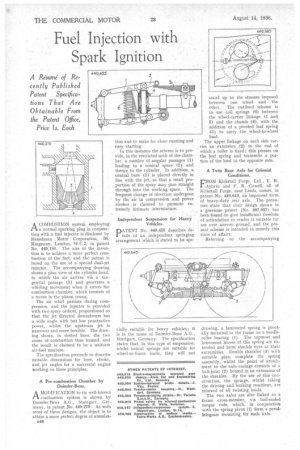
ACOMBUSTION systeni employing a normal sparking plug in conjunction with a fuel injector is disclosed by 1-lesselman Motor Corporation, 56, Kingsway, London, W.C.2, in patent No. 449,180. ' The aim of the invention is to achieve a more perfect combustion of the fuel, and the patent is based on the use of a special dual-jet injector. The accompanying drawing shows a plan view of the cylinder head, in which the air arrives via a tangential passage (1) and generates a whirling movement when it enters the combustion chamber, which consists of a recess in the piston crown.
The air whirl persists during compression, and the injector is provided with two spray orifices, proportioned so that the jet directed downstream has a wide angle with but low penetrative power, whilst the upstream jet is narrower and more forcible. The drawing shows, in dotted lines, the two zones of combustion thus formed, and the result is claimed to be a uniform air-fuel mixture.
The specification proceeds to describe suitable dimensions for bore, stroke, and jet angles for a successful engine working on these principles.
A Pre-combustion Chamber by Daimler-Benz.
A MODIFICATION to its well-known IA combustion syktem is shown by Daimler-Benz A.G. Stuttgart, Germany, in patent No. 449,279. As with most of these designs, the object is to attain a more perfect degree of atomizaB40
tion and to make for clean running and easy starting.
In this instance the scheme is to provide, in the restricted neck of the chamber, a number of angular passages (1) leading to a conical space (2) and then,ce to the cylinder. In addition, a central bore (3) is placed directly in line with the jet, so that a small proportion of the spray may pass straight through into the working space. The frequent change of direction undergone by the air in compression and power strokes is claimed to promote extremely intimate intermixture.
Independent Suspension for Heavy Vehicles.
PATENT No. 449,455 describes details of an independent springing arrangement which is stated to be spe
cia ly suitable for heavy vehicles; it is 'n the name of Daimler-Benz A.G., Stuttgart, Germany. The specification states that, in this type of suspension, whilst helical springs are suitable for wheel-to-frame loads, they will not stand up to the stresses imposed between one wheel and the other. The outlined scheme is to use coil springs (6) between the wheel-carrier linkage (1 and 5) and the chassis (4), with the addition of a pivoted leaf spring (3) to carry the wheel-to-wheel load.
The upper linkage on each side carries an extension (2) to the end of which a roller is fixed ; this presses on the leaf spring and transmits a portion of the load to the opposite side.
A Twin Rear Axle for Colonial Conditions.
FROM Kirkstall Forge, Ltd., E. R. Aylwin and F, R. Cowell, all of Kirkstall Forge, near Leeds, comes, in patent No. 449,643, an improved form of heavy-duty rear axle. The paten' tees -state that their design shown in , a previous patent (No. 397,957) has been -found to give insufficient freedom • of articulation to render it suitable for use over uneven ground, and the present. scheme is intended to remedy this state of affairs.
Referring to the accompanying drawing, a laminated spring is pivotally mounted to the frame on a needleroller bearing (1 ) . The topmost and lowermost leaves of this spring are extended and form shackle eyes at their extremities. Double shackles (3) with suitable pins, complete the spring assembly, whilst the point of attachment to the axle casings consists of a ball-joint (2) housed in an extension of the shackles. By the use of this construction, the springs, whilst taking the driving and braking reactions, are relieved of all twisting loads.
The two axles are also linked to a frame cross-member, via ball-ended torque rods, which, in conjunction with the spring pivot (I) form a parallelogram mounting for each axle.